

Navigate in Blender
Blender介面控制
Blender介面控制
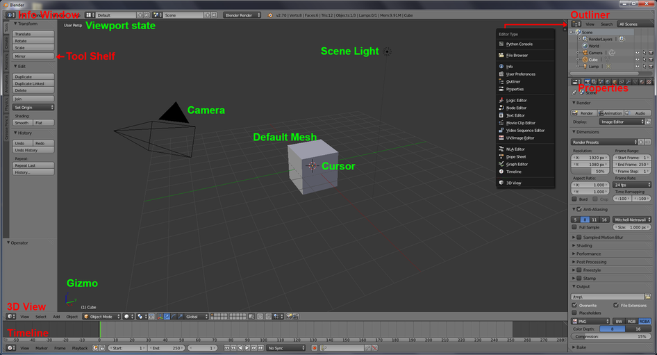
Launch Blender and you should see following layout on the screen.
開啓Blender 後的介面應如下圖
開啓Blender 後的介面應如下圖
Middle Mouse (MM) & Drag – orbit the scene
Mouse wheel / Ctrl+Middle Mouse Drag – zoom in the scene
Sht+MM Drag – pan the scene
Left Mouse (LM) & Click to locate the cursor
Right Mouse (RM) Click to select scene object. Hold Sht to multi-select or toggle selection
A key (in following, I would skip the word "key") to select all or unselect all
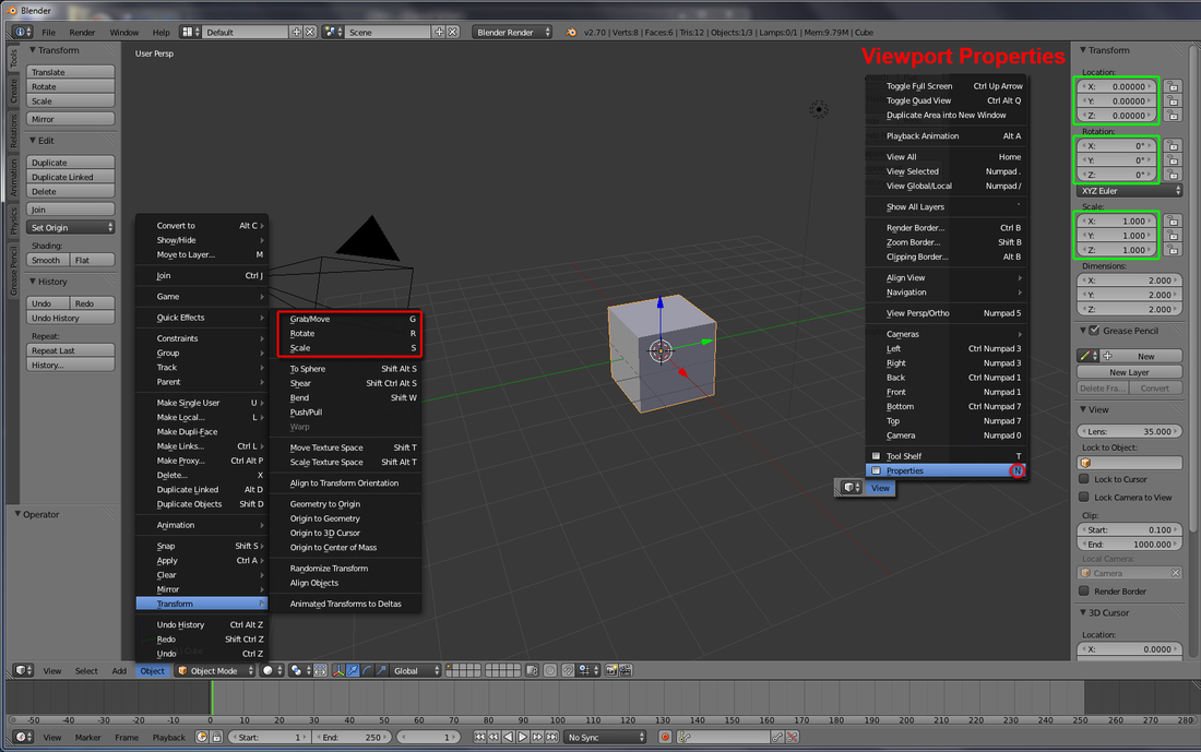
G to Move, R to Rotate, and S to Scale the selected mesh (N to launch '3D Viewport' Properties panel to read transformation information)
按住滑鼠中鍵-轉動畫面。滑鼠滾輪/Ctrl+按住滑鼠中鍵-放大縮小。Shift+按住滑鼠中鍵-平移畫面。左擊決定3D cursor位置。右擊選擇畫面內物件(按住Shift可多選/取消選擇物件)
A 鍵全選或取消全選
選取物件後,按G鍵為移動,R鍵為旋轉,S鍵為放大縮小該物件(N鍵可喚出物件詳細資料面版,查看比例變形及單位)
Mouse wheel / Ctrl+Middle Mouse Drag – zoom in the scene
Sht+MM Drag – pan the scene
Left Mouse (LM) & Click to locate the cursor
Right Mouse (RM) Click to select scene object. Hold Sht to multi-select or toggle selection
A key (in following, I would skip the word "key") to select all or unselect all
G to Move, R to Rotate, and S to Scale the selected mesh (N to launch '3D Viewport' Properties panel to read transformation information)
按住滑鼠中鍵-轉動畫面。滑鼠滾輪/Ctrl+按住滑鼠中鍵-放大縮小。Shift+按住滑鼠中鍵-平移畫面。左擊決定3D cursor位置。右擊選擇畫面內物件(按住Shift可多選/取消選擇物件)
A 鍵全選或取消全選
選取物件後,按G鍵為移動,R鍵為旋轉,S鍵為放大縮小該物件(N鍵可喚出物件詳細資料面版,查看比例變形及單位)
For a list of basic shotcut keys, pls. visit http://en.wikibooks.org/wiki/Blender_3D:_HotKeys/3D_View/Object_Mode
如需更多快捷鍵,請參考以上網址
如需更多快捷鍵,請參考以上網址
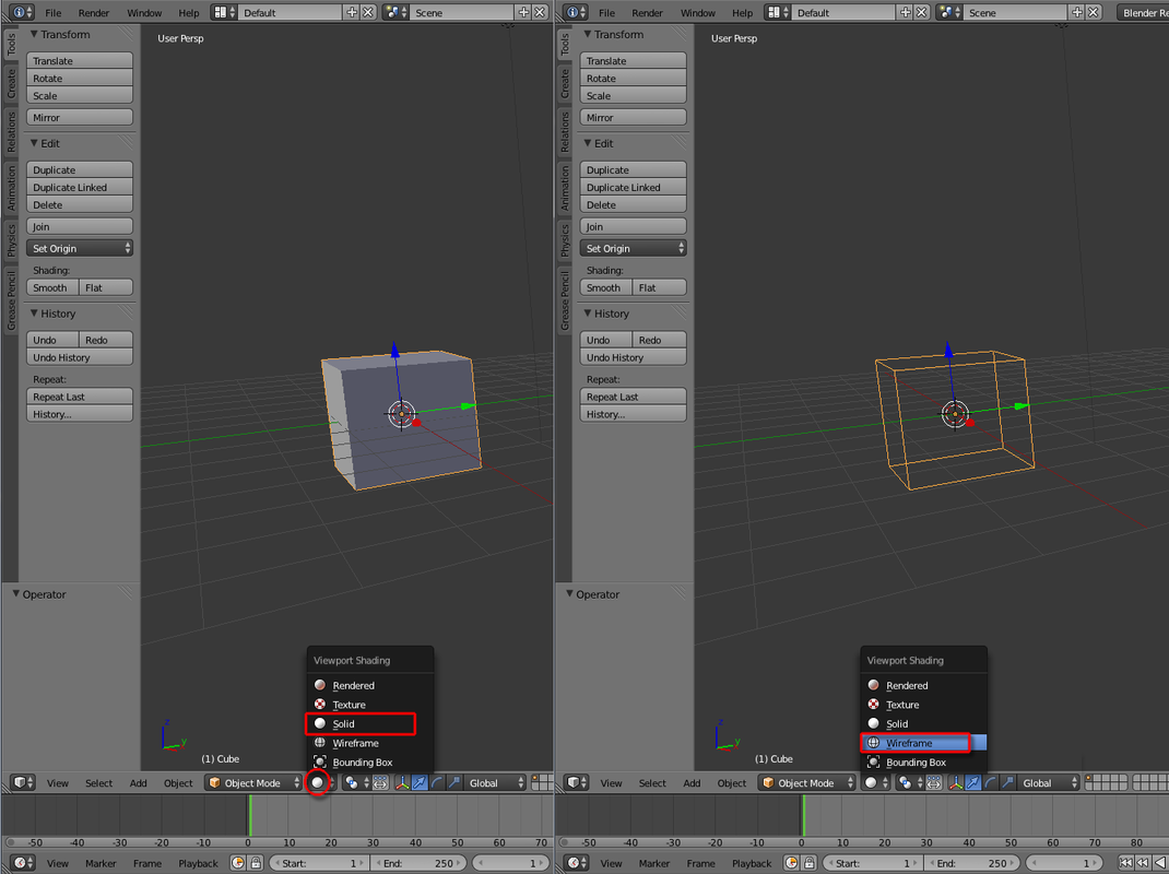
Z to toggle between ‘Solid’ and ‘Wireframe’ modes
Z 鍵切換於實體視點及格線視點之間
Z 鍵切換於實體視點及格線視點之間
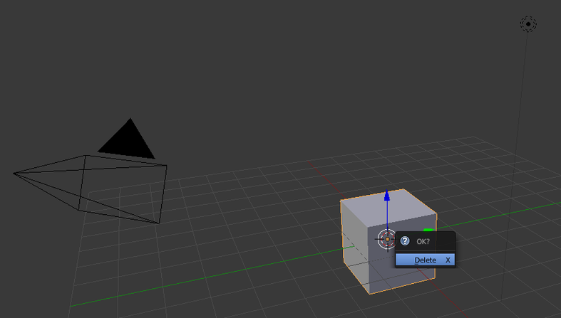
X to Delete the selected mesh
X 鍵刪除所選物件
X 鍵刪除所選物件
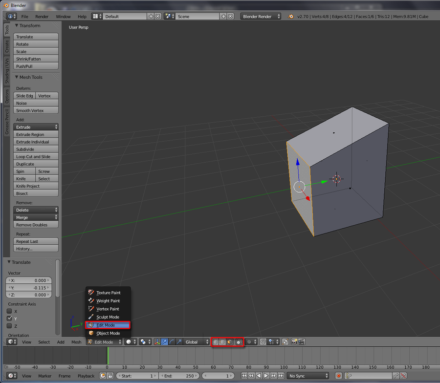
Tab key to enter 'Edit Mode' (You can manipulate with 'Vertex', 'Edge' or 'Face' mode. Choose 'Select to Visible' to see through the mesh if needed)
Tab 鍵切換於物件模式和編緝模式之間(有 'Vertex, Edge 及 Face mode。也可選 'Select to Visible'來透視模型)
Tab 鍵切換於物件模式和編緝模式之間(有 'Vertex, Edge 及 Face mode。也可選 'Select to Visible'來透視模型)
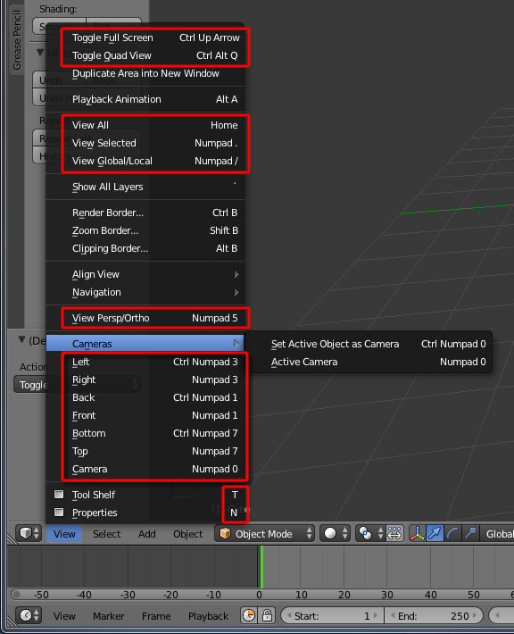
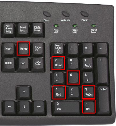
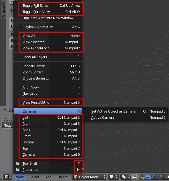
Use Number pad shortcut key or ‘View’ menu to change to Orthographic views.
Home key to view all
"." (period key in Numpad) to view selection
使用數字鍵盤之快捷鍵/按View選單切換視角
「Home」鍵檢視全部
「.」鍵(數字鍵盤上)檢視所選物件
Home key to view all
"." (period key in Numpad) to view selection
使用數字鍵盤之快捷鍵/按View選單切換視角
「Home」鍵檢視全部
「.」鍵(數字鍵盤上)檢視所選物件
|
|
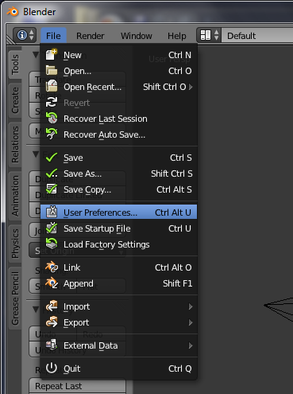
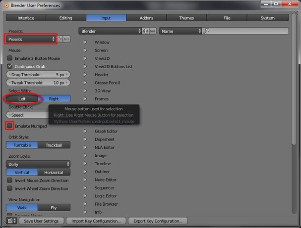
Goto File >User Preferences > 'Input' tab: ‘Select With:’ to change ‘Select With’ “Left”(LM) or goto ‘Presets’ to choose either MAX or MAYA manipulation style.
可以在File>User Preferences>Select With 選項:設定以左鍵選取 或 前往Presets選擇MAX或MAYA模式
可以在File>User Preferences>Select With 選項:設定以左鍵選取 或 前往Presets選擇MAX或MAYA模式
|
|
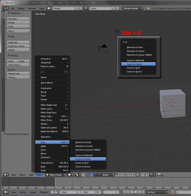
Use of Cursor
Sht + S > Snap Cursor to ~
3D cursor之用法
Shift+S>Snap cursor to~ 選項分別將3D cursor調整到不同位置
Sht + S > Snap Cursor to ~
3D cursor之用法
Shift+S>Snap cursor to~ 選項分別將3D cursor調整到不同位置
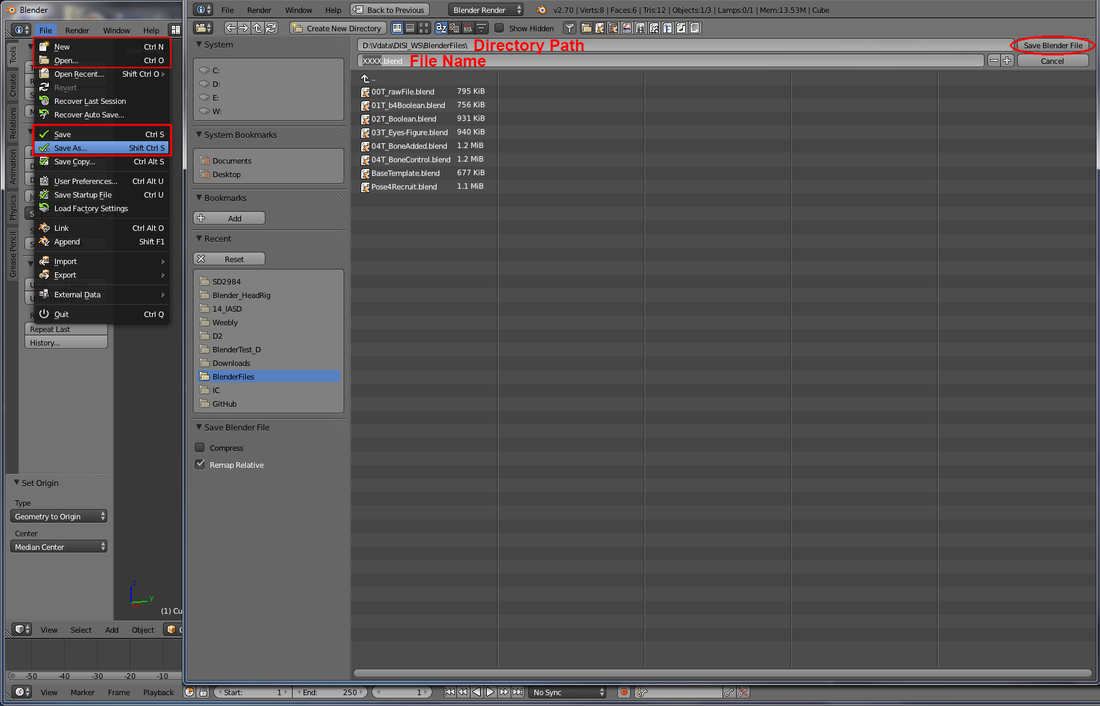
Sht+Ctrl+S – save Scene
Shift+Ctrl+S-儲存檔案
Shift+Ctrl+S-儲存檔案
Basic Polygonal Modeling (for 3DP)
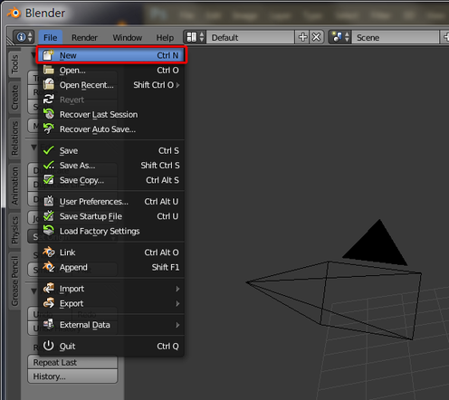
1. File > New, or Ctrl + N to start a new scene.
1. File > New, or Ctrl + N to start a new scene.
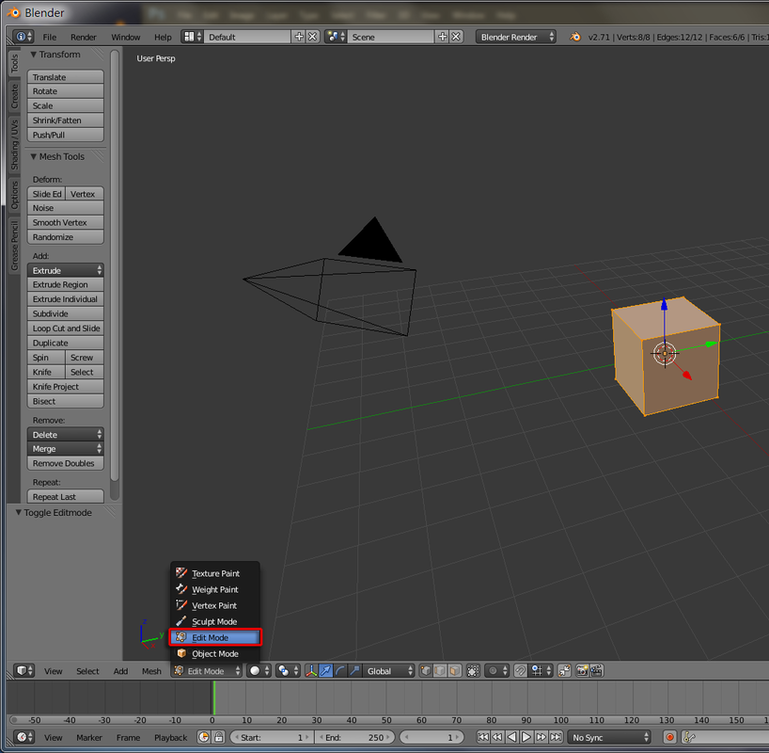
2. Switch to Edit Mode. (Tab key for shortcut)
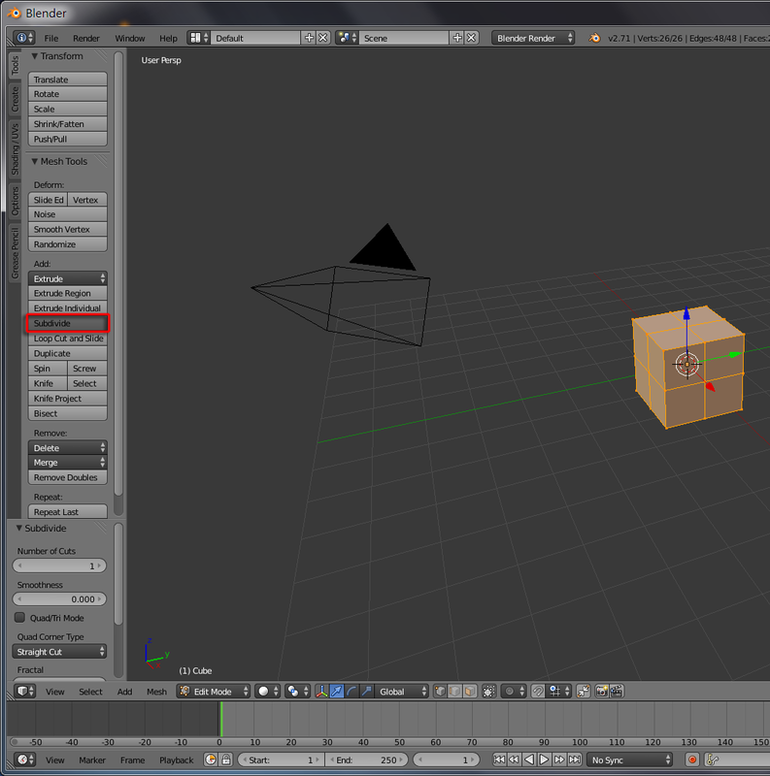
3. Tool Shelf > Tools > Add: Subdivide
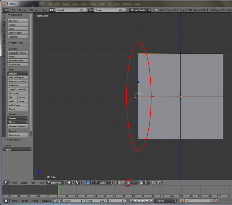
4. Hit B key to "Border Select" the left hand sided vertices. Make sure the "Limit to Visible" button is on.
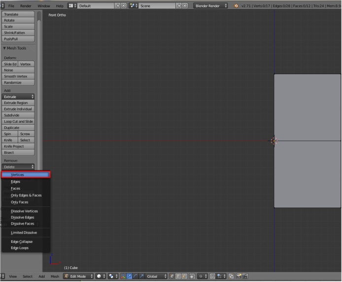
5. Tool Shelf > Tools > Remove: Delete > Vertices
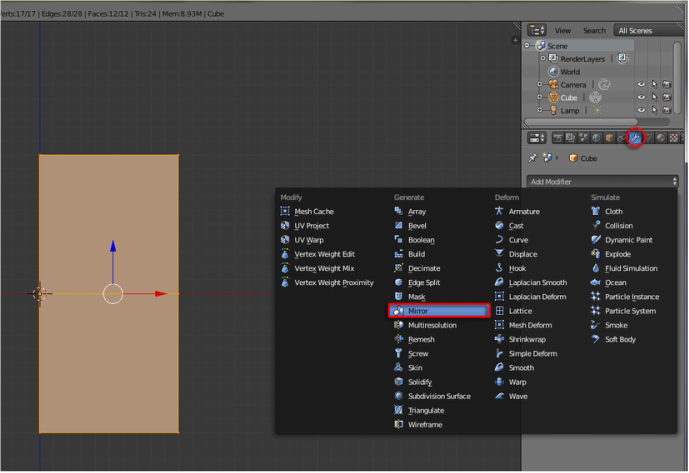
6. Properties Shelf > Modifier > Add Modifier > Generate: Mirror
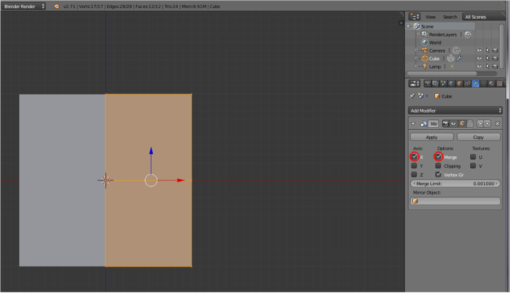
7. Leave the default setting to select X Axis and Merge Options
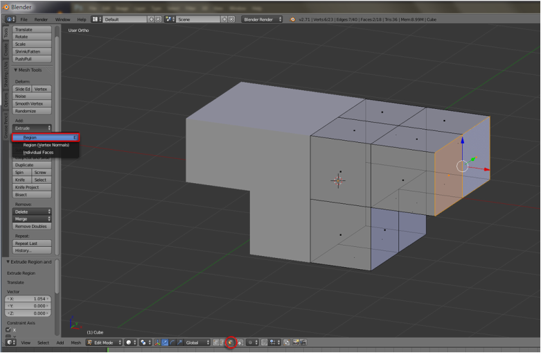
8. Switch to Faces mode. Select both the faces on top right hand side. Tool Shelf > Tools > Add: Extrude > Region (or hit E for shortcut key) and drag to extrude the arm. Do it once more to extrude a forearm.
9. Do the same to create the leg.
10. Switch to Object mode. Hit Apply inside the Mirror panel.
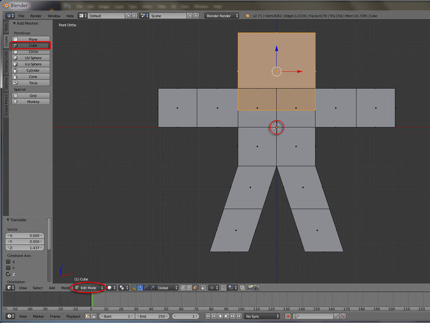
11. Switch to Edit mode. Make sure cursor is in center and goto Tool Shelf > Create > Cube. Grab Z to place it as head.
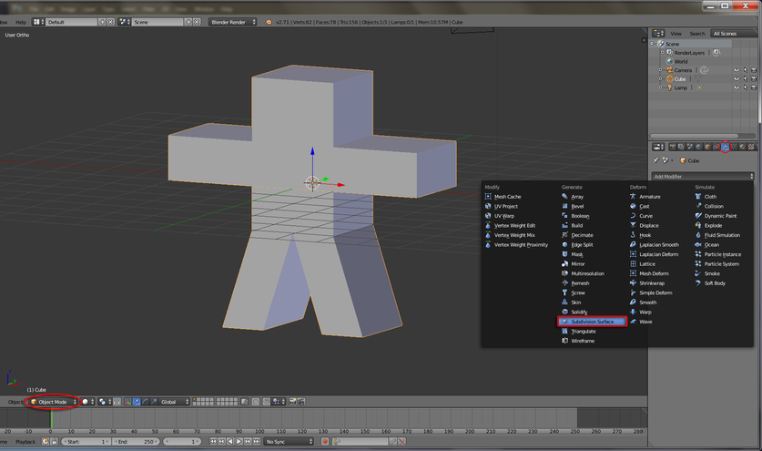
12. Switch to Object mode. Properties Shelf > Modifier > Add Modifier > Subdivision Surface.
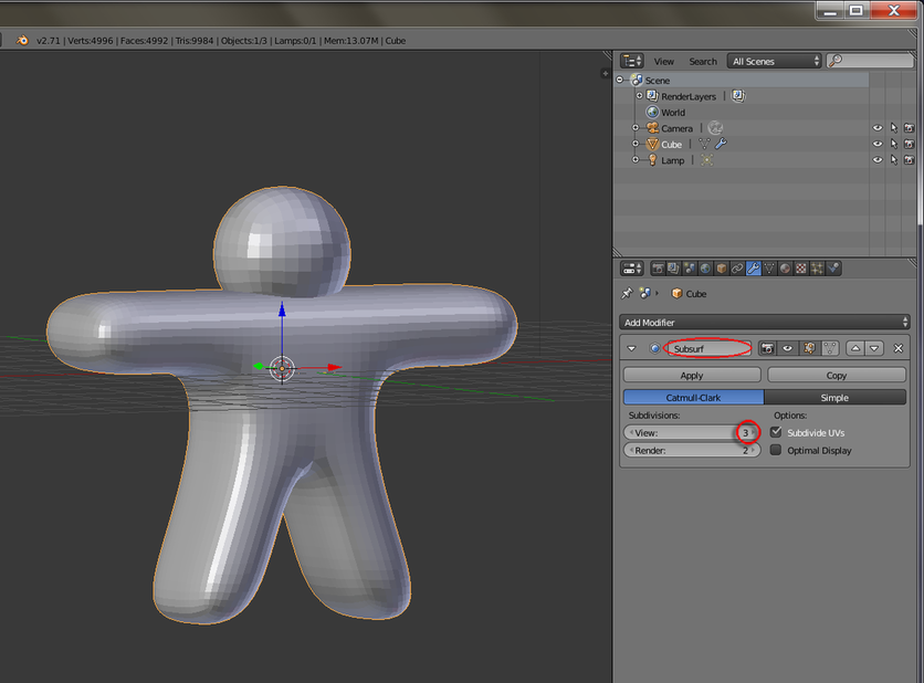
13. Inside the panel, Input 3 for Subdivision view level.
13. Inside the panel, Input 3 for Subdivision view level.
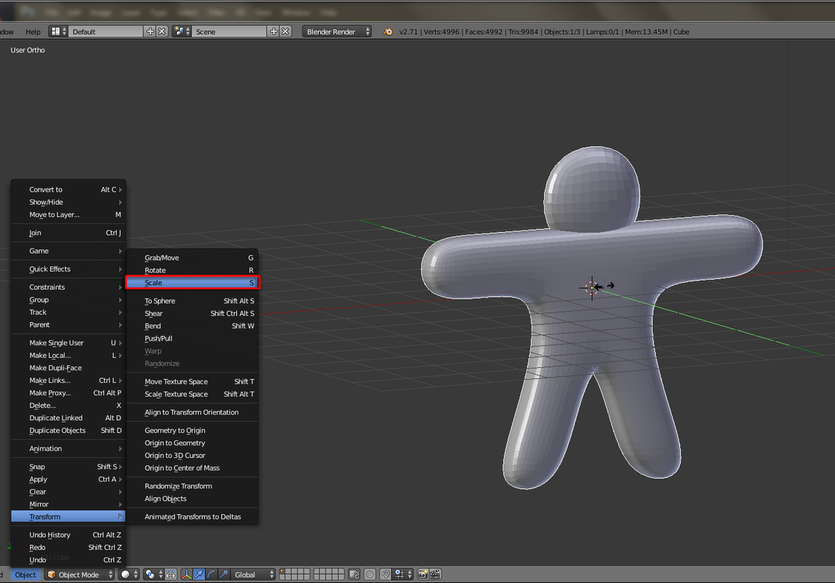
14. Scale Y to reduce the thickness.
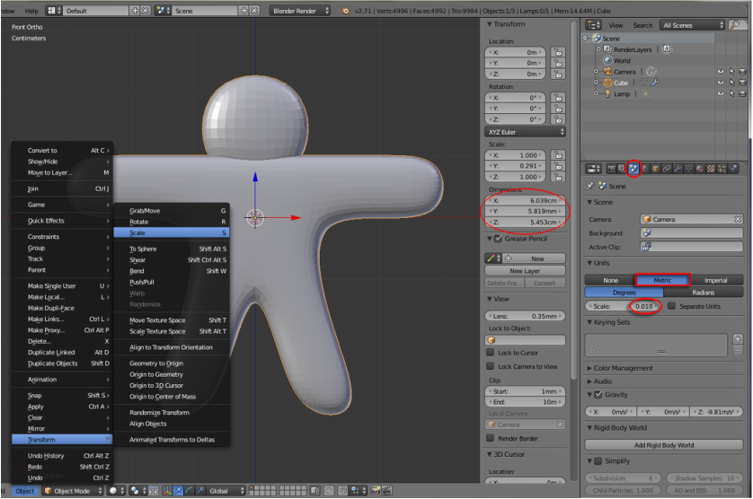
15. Properties Shelf > Scene > Units: Metric. Change Scale to 0.01 and check it's Dimensions in the Properties panel. Scale the model up or down if needed.
16. Switch to Edit mode. Tool Shelf > Create > Ico Sphere. Input Size 1mm and Grab X and Z to locate the eye.
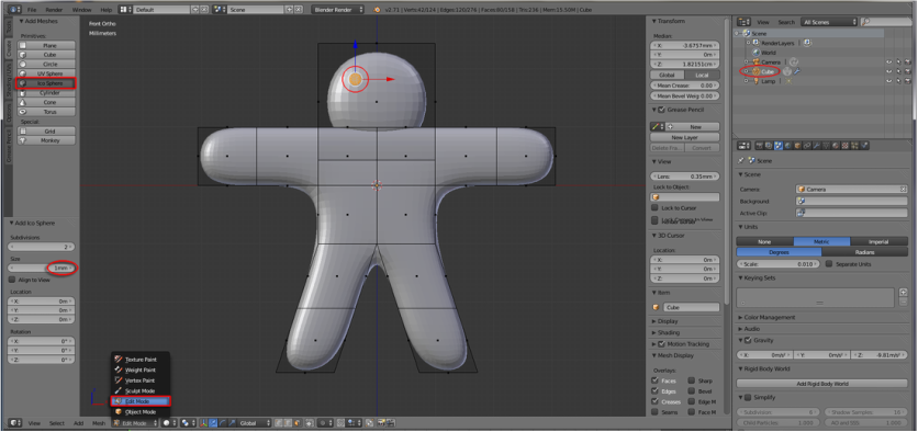
17. Grab and Scale Y to fix it's location and dimension.
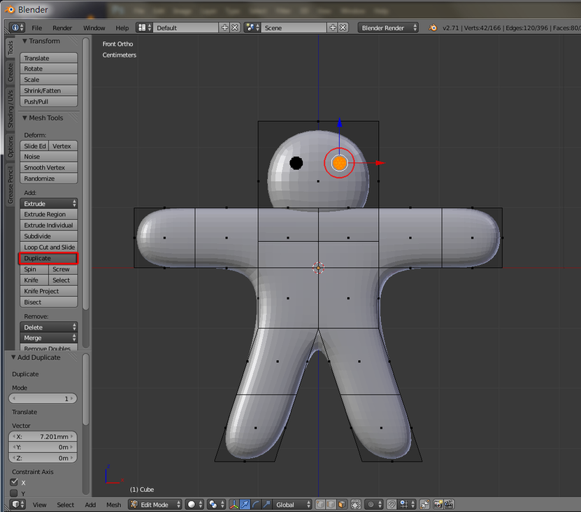
18. Tools > Add: Duplicate and Grab X to local the other eye.
19. Duplicate a few more times to create a mouth and several buttons.
19. Duplicate a few more times to create a mouth and several buttons.
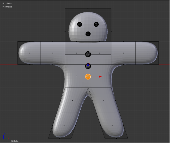
20. Select vertices (or hit B to apply border selection tool). Rotate and Grab to shape his limbs.
21. Switch to Object mode. Properties Shelf > Modifier > Apply Subdivision Surface. Double check the dimension and make sure there is only one geometry model in the scene.
22. Switch to Edit mode. Hit A to select all vertices. Tools > Remove: Remove Doubles to delete extra vertices.
23. Hit A again to unselect all vertices. Hold Sht + Ctrl + Alt + M to launch Non Manifold command.
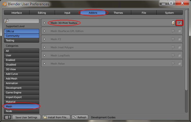
24. File > User Preferences.. > Addons. Firstly select Mesh from Categories, then check "Mesh: 3D Print Toolbox".
25. Tool Shelf > 3D Printing > Check All to double check the model is printable
26. Select your output folder under "Export Path:". Choose STL under Format and Export the model file. (Different 3D printers would accept other file formats and STL is the most common one)

Character Modeling (for 3DP)
人物建模(輸出至3D打印)
人物建模(輸出至3D打印)
1. File > New, or Ctrl +N to start a new scene.
2. Switch to Edit Mode. (Tab key)
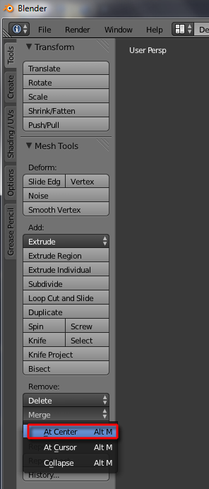
3. Tool Shelf > Mesh Tools > Merge > At Center, and choose “At Center”.
1. File>New或按Ctrl+N開啟新場景
2. 切換至編緝模式(按Tab鍵)
3. 打開 Tool Shelf > Mesh Tools > Merge >選項按"At Center"
2. Switch to Edit Mode. (Tab key)
3. Tool Shelf > Mesh Tools > Merge > At Center, and choose “At Center”.
1. File>New或按Ctrl+N開啟新場景
2. 切換至編緝模式(按Tab鍵)
3. 打開 Tool Shelf > Mesh Tools > Merge >選項按"At Center"
4. Window Header > View > Front, or Numpad key "1" and move on next step to proceed Extrude > Vertices Only
4. 選Window Header>View>Front,或按數字鍵盤'1' 。繼續下一步進行Extrude功能
4. 選Window Header>View>Front,或按數字鍵盤'1' 。繼續下一步進行Extrude功能
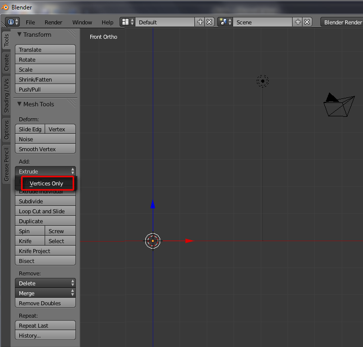
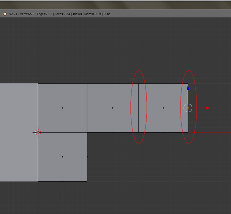
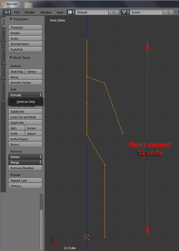
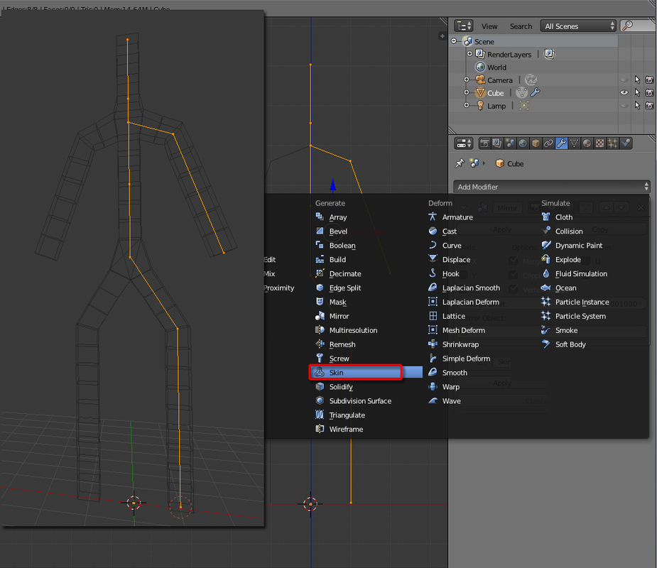
5. Tool Shelf > Mesh Tools > Add: Extrude > Vertices Only. Hit Z key once to constraint to Z axis. Repeat the Extrude command (or hit E for shortcut key) to complete half of the skeleton for your character, alike the figure below.
5. 打開Tool Shelf > Mesh Tools > Add: Extrude > 下按 Vertices Only ,按一下Z鍵使其固定於Z軸上。重覆按Extrude(或可以按快捷鍵E)移動點,直至完成半邊骨架(見下圖)(於這workshop, 請勿長於十二格)
5. 打開Tool Shelf > Mesh Tools > Add: Extrude > 下按 Vertices Only ,按一下Z鍵使其固定於Z軸上。重覆按Extrude(或可以按快捷鍵E)移動點,直至完成半邊骨架(見下圖)(於這workshop, 請勿長於十二格)
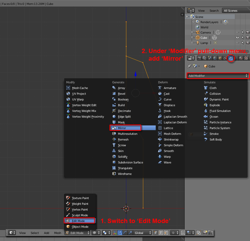
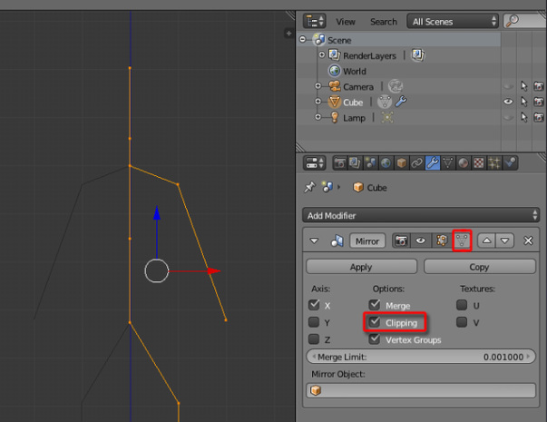
6. Firstly switch to ‘Edit Mode’, or hit Tab doing so. Then on the right hand side’s ‘Properties’ window, select ‘Modifier’ tab, and click the ‘Add Modifier’ to access its pull-down menu, choose “Mirror”.
6. 首先切換至編緝模式(按Tab鍵),於右邊功能列中找到Modifier頁,按 Add modifier>Mirror
6. 首先切換至編緝模式(按Tab鍵),於右邊功能列中找到Modifier頁,按 Add modifier>Mirror
7. Inside the Mirror panel, check ‘Clipping’. Also, check the ‘Editing cage’ to preview the other side (not a must).
7. 於Mirror控制欄內點選Clipping;點選Editing cage以預視效果(如需要)
7. 於Mirror控制欄內點選Clipping;點選Editing cage以預視效果(如需要)
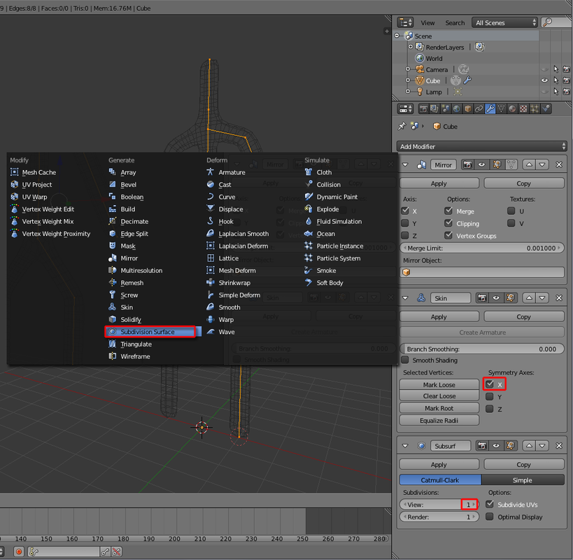
8. Use ‘Add Modifier’ menu again to add “Skin” modifier. Select “X” under the Symmetry Axes.
8. 再按Add Modifier>Skin,於Axis欄下剔選"X"
8. 再按Add Modifier>Skin,於Axis欄下剔選"X"
9. Use ‘Add Modifier’ once more to add “Subdivision Surface”. Set ‘View’ level to “1”.
9. 再按Add Modifier,選擇Subdivison Surface,設定View值為"1 "
9. 再按Add Modifier,選擇Subdivison Surface,設定View值為"1 "
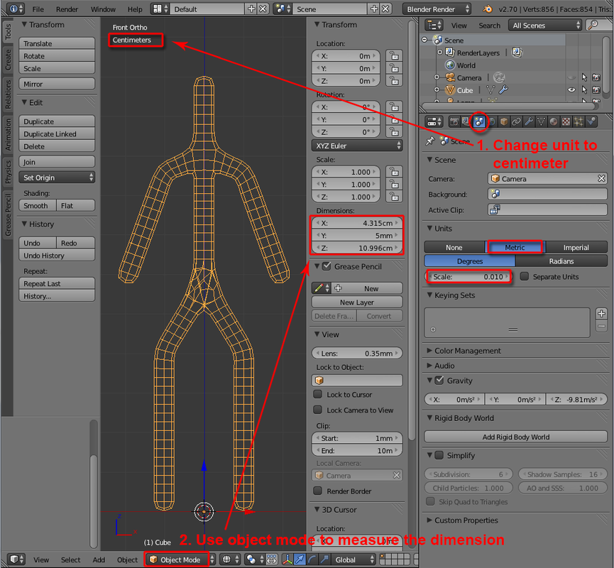
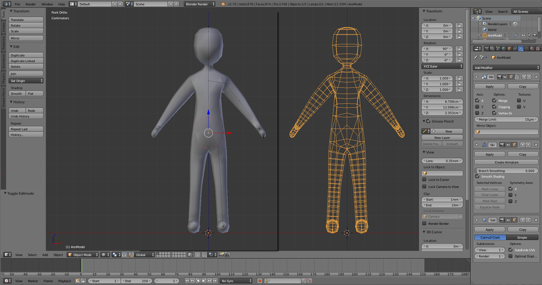
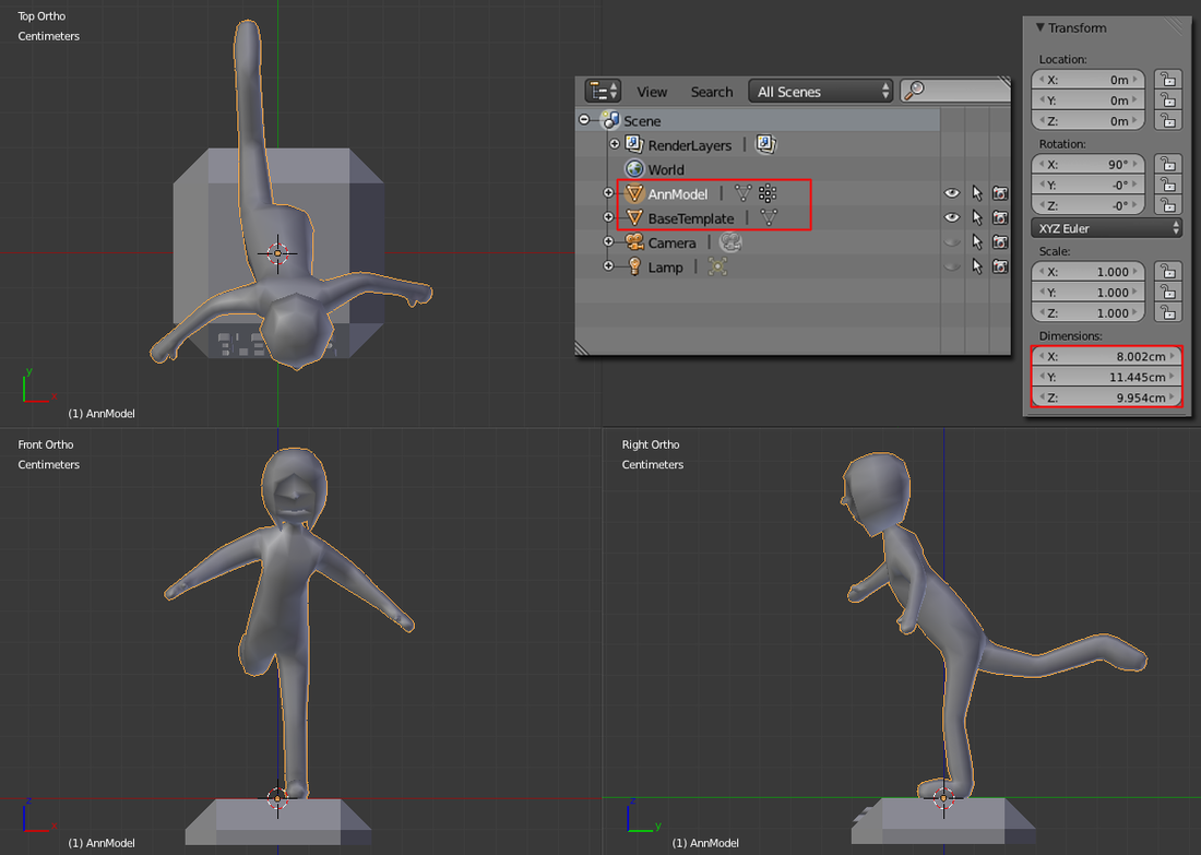
10. On the right hand side’s Properties Window, select ‘Scene’ tab, then under ‘Units’ section, click “Metric” and set ‘Scale’ to “0.01”. You should now read from the 3D View port displaying ‘Centimeters’ as the unit. Switch to “Object Mode” and hit N to launch 3D View’s Properties panel or goto Window Header > View > Properties to do so. You now can read the dimension of your character’s skeleton. (limit it to 12 cm3 for the meantime in this workshop!)
10. 於右邊功能列找到scene頁,於Units之下按Metric,設定scale為0.01,現在你可以在於3D畫面中見到物件單位為 ‘Centimeters’。切換至物件模式(Tab鍵)再按N鍵喚出 Properties版面 或 於選項欄中按View>Properties,你現在可以看到物件之呎寸(請控制於12x12x12cm之內)
10. 於右邊功能列找到scene頁,於Units之下按Metric,設定scale為0.01,現在你可以在於3D畫面中見到物件單位為 ‘Centimeters’。切換至物件模式(Tab鍵)再按N鍵喚出 Properties版面 或 於選項欄中按View>Properties,你現在可以看到物件之呎寸(請控制於12x12x12cm之內)
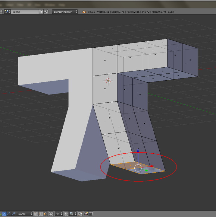
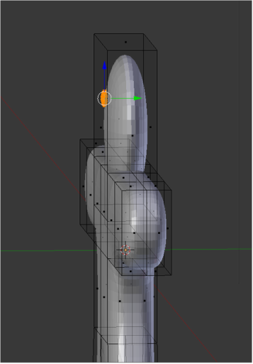
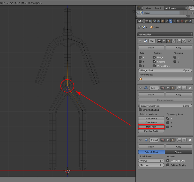
11. Return to “Edit Mode”. Highlight the pelvis point of your character (alike the picture underneath), then inside Properties Window’s ‘Skin’ section, click “Mark Root”.
11. 回到編緝模式,點選骨盆的中心點(如圖所示),然後於右邊功能列Skin頁中,按"Mark root "
11. 回到編緝模式,點選骨盆的中心點(如圖所示),然後於右邊功能列Skin頁中,按"Mark root "
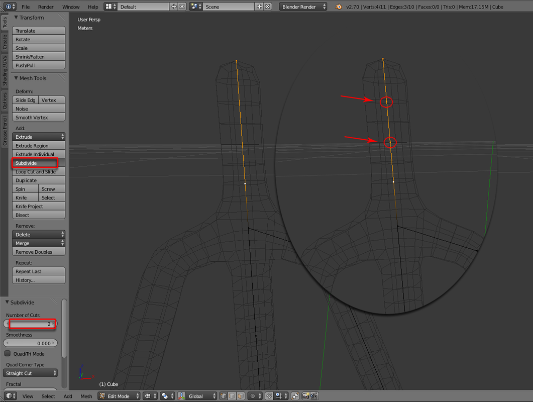
12. When extra vertex is needed in a bone, firstly highlight the two vertices. In the Tool Self > Mesh Tools > “Subdivide”, and if you need two extra vertices instead, change the value of ‘Number of Cuts’ to “2”.
12. 如需要增加控制點,請先點選頭尾點,然後於Tool shelf>Mesh tool中點選Subdivide;如需增加兩個點,可於左欄 ‘Number of Cuts’ 下輸入2,如此類推。
12. 如需要增加控制點,請先點選頭尾點,然後於Tool shelf>Mesh tool中點選Subdivide;如需增加兩個點,可於左欄 ‘Number of Cuts’ 下輸入2,如此類推。
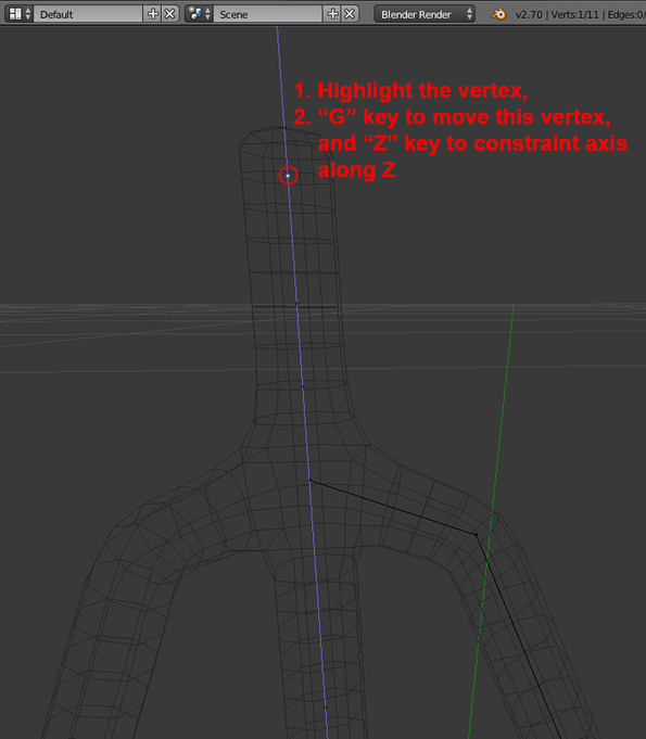
13. If you need to adjust position of the inserted vertex, highlight it, then goto Window Header > Mesh > Transform > Grab/Move, or use shortcut key G to do so. Click Z once to constraint Z axis.
13. 如需調整新增控制點的位置,先選擇該點,於選項欄按Mesh>Transform>Grab/Move,或可以直接按G鍵移動,再按Z鍵使其只沿住Z軸移動
13. 如需調整新增控制點的位置,先選擇該點,於選項欄按Mesh>Transform>Grab/Move,或可以直接按G鍵移動,再按Z鍵使其只沿住Z軸移動
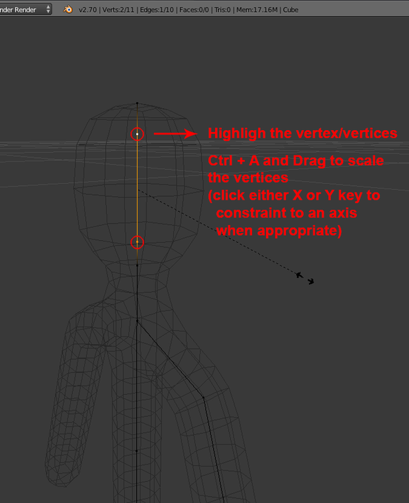
14. When need to scale the vertex skin, highlight all the appropriate vertices. Ctrl +A and Drag to scale up or down. (you can hit X or Y key to set constraint to the axis if needed).
14. 如需調整skin的大小,先選取該點,按Ctrl+A拉動即可放大縮小(可以再按X或Y使其沿住其軸變形)
14. 如需調整skin的大小,先選取該點,按Ctrl+A拉動即可放大縮小(可以再按X或Y使其沿住其軸變形)
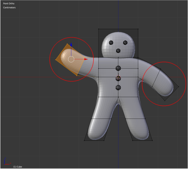
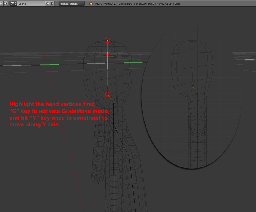
15. Whenever need to move vertices, highlight them, then goto Window Header > Mesh > Transform > Grab/Move, or use shortcut key G to do so. Click Y once to constraint to Y axis.
15. 如需調整頭部控制點的位置,先選擇該點,於選項欄按Mesh>Transform>Grab/Move,或可以直接按G鍵移動,再按鍵Y使其只沿住Y軸移動
15. 如需調整頭部控制點的位置,先選擇該點,於選項欄按Mesh>Transform>Grab/Move,或可以直接按G鍵移動,再按鍵Y使其只沿住Y軸移動
16. Keep inserting extra vertices and then carefully sculpt the body shape with Scale and Grab/Move tools. *Download and feel free to use “01_BipedTemplate.blend” to polish up your own biped character (or download other available scenes as wish).
16. 增加控制點並用放大/縮小/移動等方法加以調整,直至畫出身體基本形狀(可以下載“01_BipedTemplate.blend”作為基底或選擇其他範本)
16. 增加控制點並用放大/縮小/移動等方法加以調整,直至畫出身體基本形狀(可以下載“01_BipedTemplate.blend”作為基底或選擇其他範本)
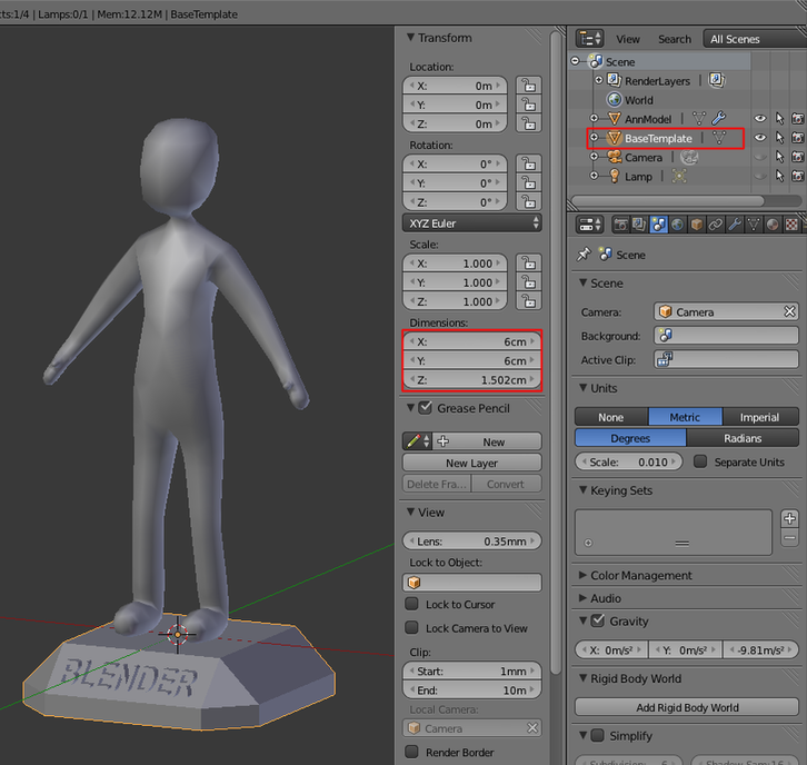
17. After finishing the basic shape of your character (would build details later), and check your model is within 13 cm3 at this stage. We now import the ‘Base Template’ for easy posing your character.
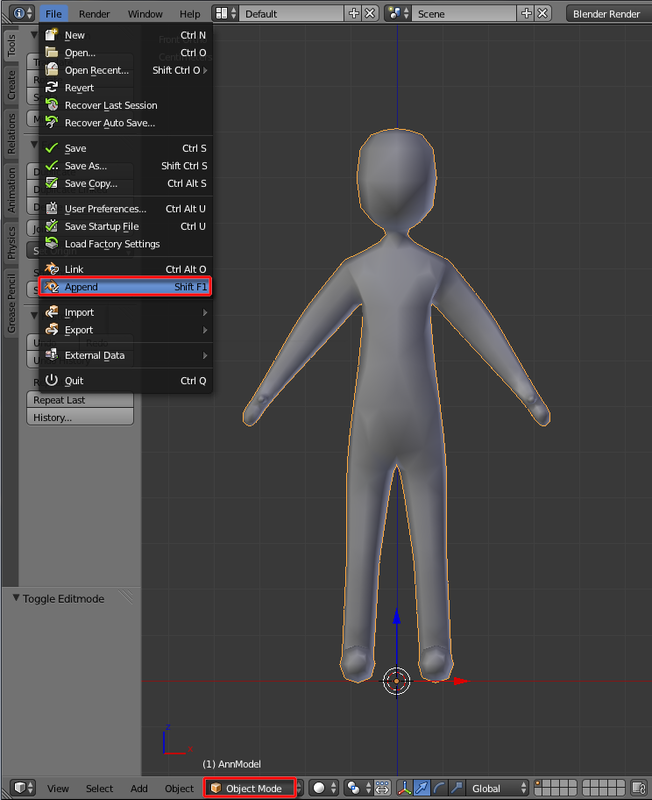
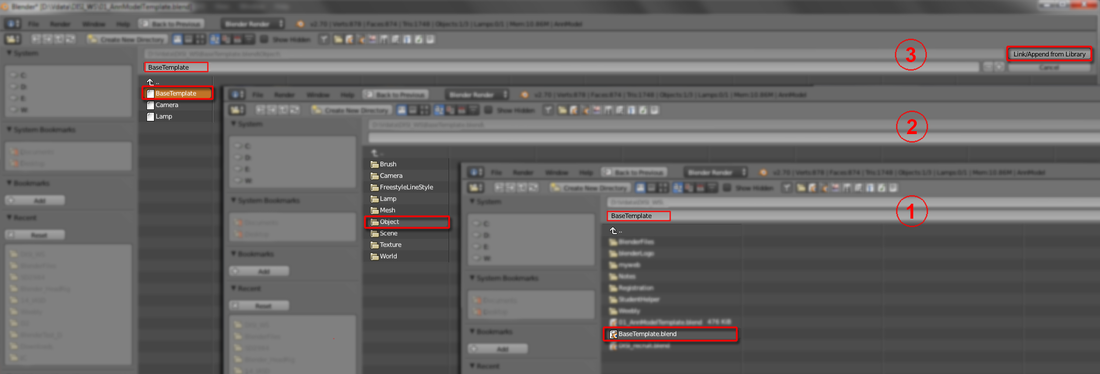
Switch to “Object Mode” first, then File > Append and goto the folder you saved the “BaseTemplate.blend” and click this file name. Then select “Object folder” from the list. Lastly, select once more “BaseTemplate” and click 'Link/Append from Library' to complete the appending.
17. 完成基形後,請確認其大小暫時不超過13x13x13cm。以下步驟為載入Base Template方便擺弄造型。切換至物件模式(Tab鍵)於左上角選File>Append,找到Base Template.blend並點擊該檔名。再選擇文件夾Object,選擇BaseTemplate並按Link/Append from Library
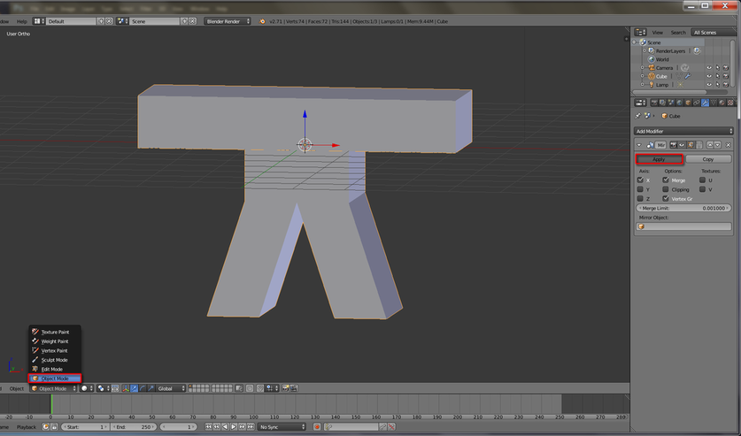
18. Highlight the model mesh, inside ‘Mirror modifier’ panel, hit “Apply”, then hit “Create Armature” under the “Skin modifier” panel. Switch from Object Mode to “Pose Mode”, select any bone to Rotate the joint, or use R key to do so.
18. 選取人物模型,於右邊Mirror panel內點擊Apply,再於Skin panel下點擊Create Armature。從物件模式切換至動作模式(Pose Mode),選取任何一條骨,按R鍵可以旋轉
18. 選取人物模型,於右邊Mirror panel內點擊Apply,再於Skin panel下點擊Create Armature。從物件模式切換至動作模式(Pose Mode),選取任何一條骨,按R鍵可以旋轉
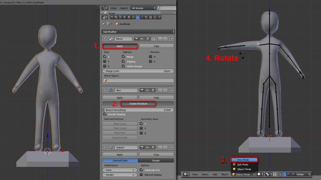
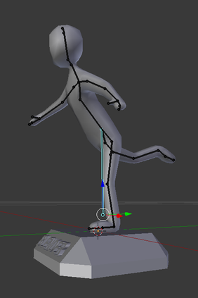
19. Use 'Rotate' and 'Grab/Move' tool to pose your character on the base platform (you can design your character’s posture) and make sure the final combined mesh won’t exceed 15 cm3.
19. 用旋轉(R),和移動(G)鍵擺出理想的姿勢,並且把人物模型安放於底座上。請確認模型和底座總共不超過15x15x15cm
19. 用旋轉(R),和移動(G)鍵擺出理想的姿勢,並且把人物模型安放於底座上。請確認模型和底座總共不超過15x15x15cm
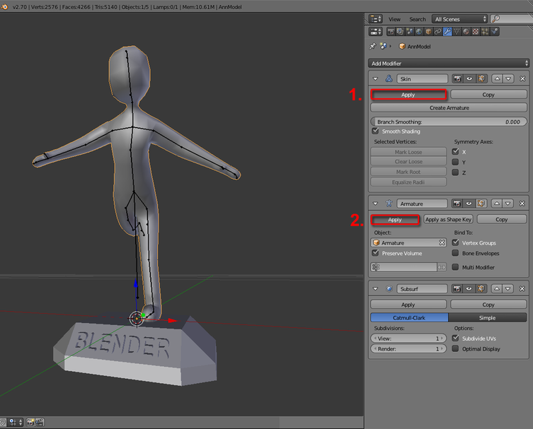
20. Select the character mesh, inside the "Skin modifier" panel, hit 'Apply' to confirm the mesh. Then hit 'Apply' inside "Armature modifier" to confirm the posture. (You can't use the bone to change posture after committed this)
20. 選取人物模型,於Skin modifier面版中點擊Apply確認。再於Armature modifier中按Apply確定其姿勢。(之後不能用骨架)
20. 選取人物模型,於Skin modifier面版中點擊Apply確認。再於Armature modifier中按Apply確定其姿勢。(之後不能用骨架)
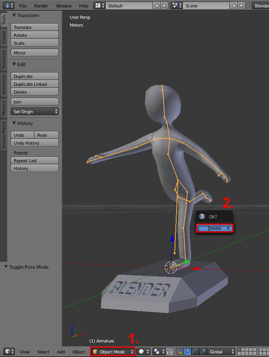
21. Select the Armature bones in “Object Mode” and hit X (Delete key) to confirm deleting the armature.
21. 於物件模式之下選取骨架,按X確認刪除骨架
21. 於物件模式之下選取骨架,按X確認刪除骨架
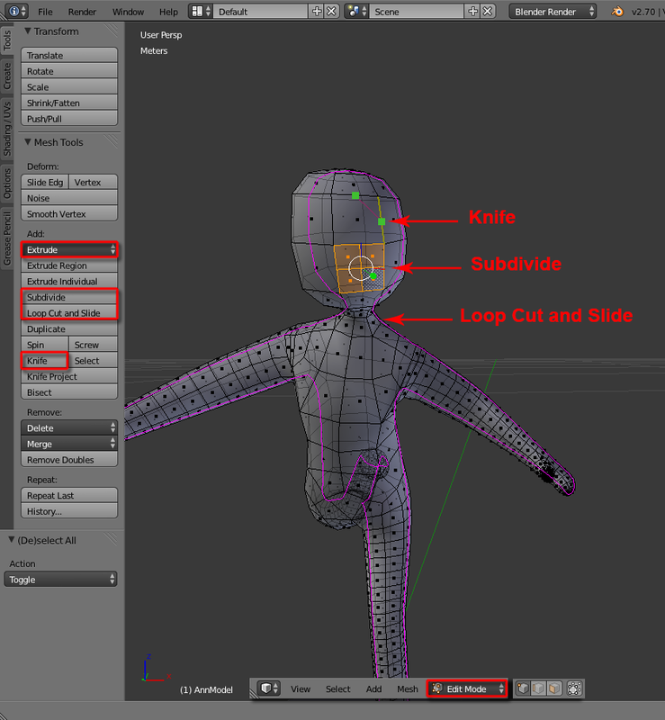
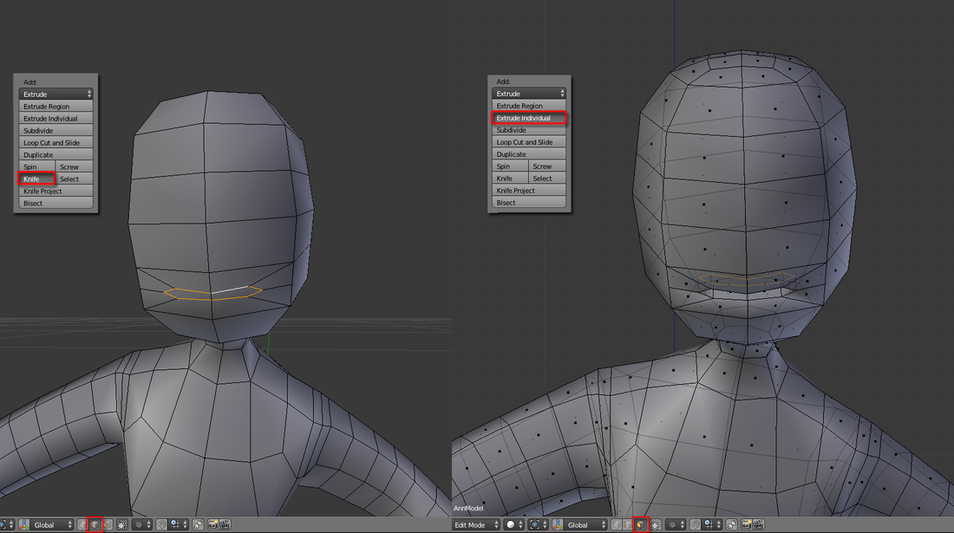
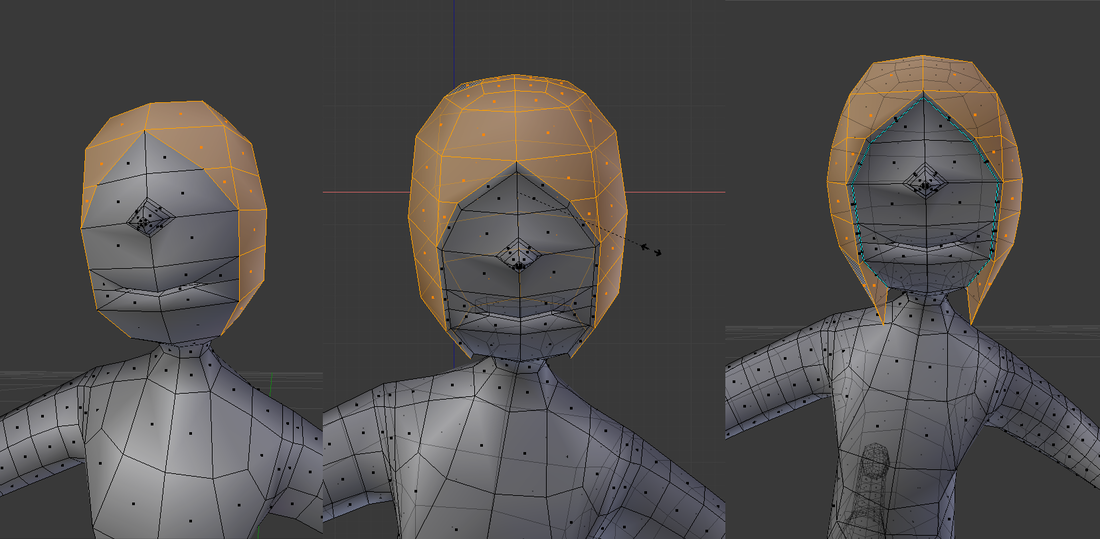
22. Switch to “Edit Mode” (select Vertex/Edge/Face mode whenever appropriate) and use any Mesh Add Tools (Extrude, Subdivide, Loop Cut and Slide, and Knife) to insert details for your character model. Finally, check out your model and base meshes total dimension.
22. 切換到編緝模式(選取任何一點/線/面)並用所有方法(拉出Extrude,平分Subdivide,環切loop cut,自由刀切knife等等)以增加模型細節。最後確認其大小符合這workshop。
22. 切換到編緝模式(選取任何一點/線/面)並用所有方法(拉出Extrude,平分Subdivide,環切loop cut,自由刀切knife等等)以增加模型細節。最後確認其大小符合這workshop。
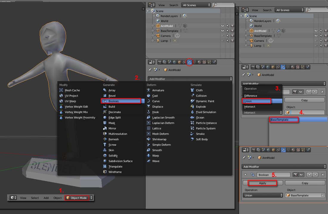
23. In “Object Mode”, add 'Boolean modifier', and inside Boolean panel, choose 'Union' under Operation and select the 'BaseTemplate' under Object’s pull down menu. Finally hit 'Apply'.
23.於物件模式中,加一個Boolean modifier,在Operation下選Union,在Object下選BaseTemplate,然後按Apply
23.於物件模式中,加一個Boolean modifier,在Operation下選Union,在Object下選BaseTemplate,然後按Apply
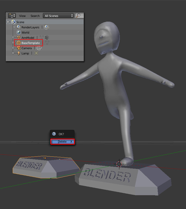
24. In either “Outliner” or “3D View”, “Delete” the extra “BaseTemplate” mesh.
24. 於右上角Outliner或直接在3D畫面中,選取BaseTemplate模型並刪除
24. 於右上角Outliner或直接在3D畫面中,選取BaseTemplate模型並刪除
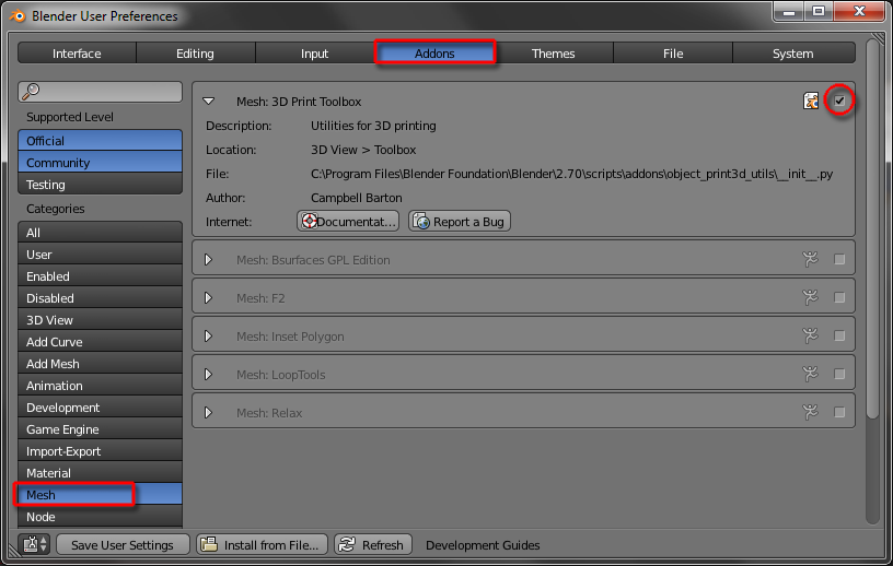
25. Goto File > User Preferences, and choose 'Addons' tab, under Categories, select “Mesh” and check the “Mesh: 3D Print Toolbox”.
25. 前往File>User Preferences>Addons,於分類中選取Mesh,剔選Mesh:3D Print Toolbox
25. 前往File>User Preferences>Addons,於分類中選取Mesh,剔選Mesh:3D Print Toolbox
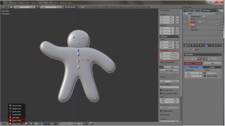
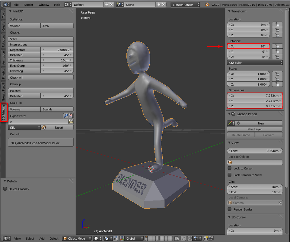
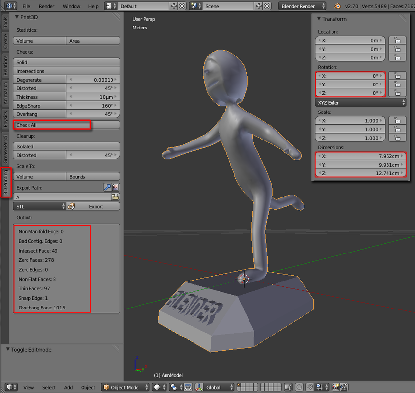
26. Inside the ‘Tool Shelf’ panel, open the “3D Printing” tab but in this case, in the 3D View’s Properties panel, there is a minor problem though the volume does not exceed this workshop’s limitation.
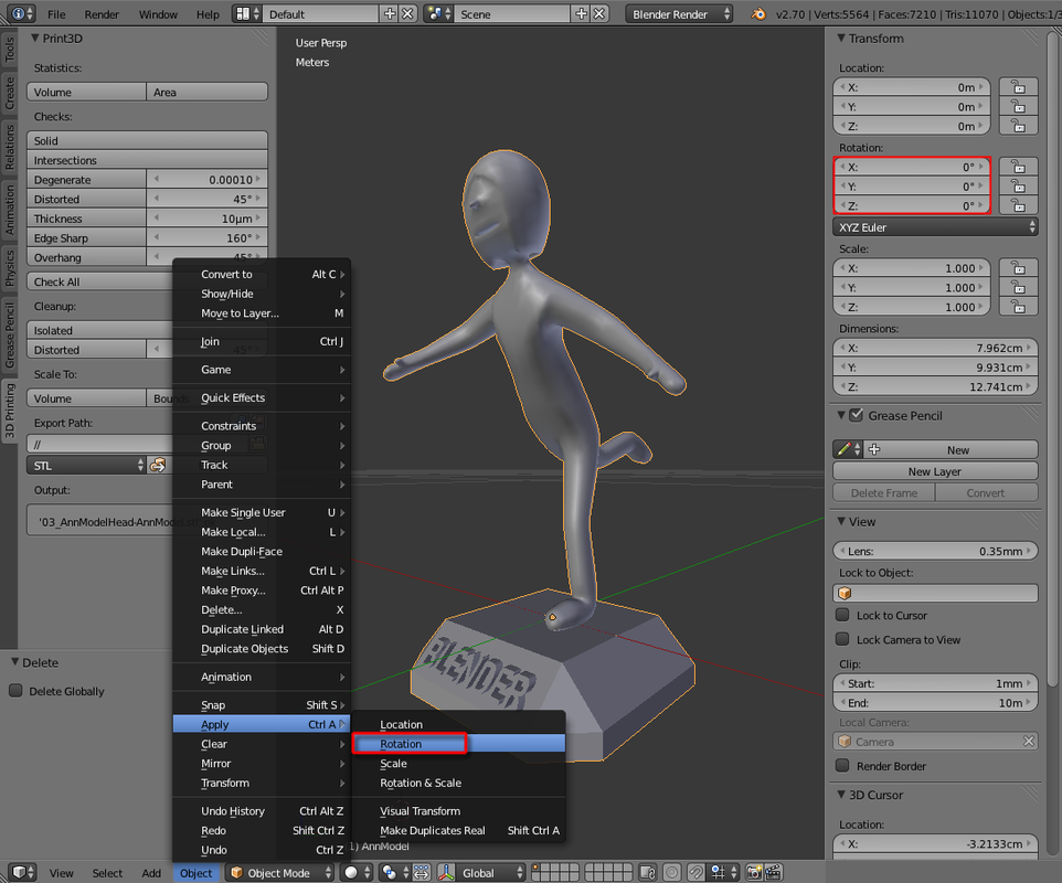
To fix this Rotation X problem, select Object > Apply > Rotation.
26. 於左邊tool shelf面版中,打開3D Printing分頁。於右邊詳細資料面版中,可看到X旋轉了90度;於下方選項中按Object > Apply > Rotation即可解決
To fix this Rotation X problem, select Object > Apply > Rotation.
26. 於左邊tool shelf面版中,打開3D Printing分頁。於右邊詳細資料面版中,可看到X旋轉了90度;於下方選項中按Object > Apply > Rotation即可解決
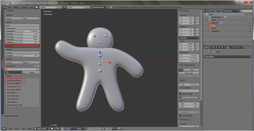
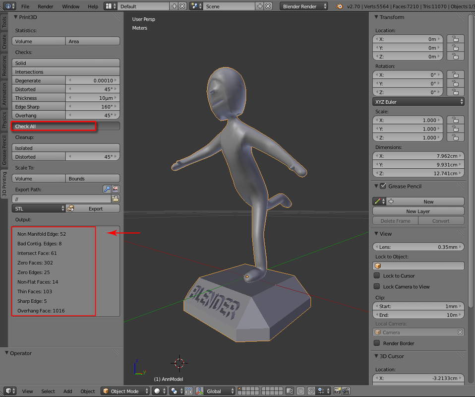
27. Inside the ‘3D Printing’ tab’s Checks feature, select 'Check All' and there is a report on ‘Non Manifold Edges’ problem in this case (non manifold edges are bad for 3D printing since some edges have more than 2 adjoining faces, we need to identify them and fix these offending parts).
27. 於3D printing分頁中,於Check欄下按 'Check All'。可見例中有Non Manifold Edges問題(因有兩個或以上的線重叠而產生的問題,有礙3D打印,須要找出問題部分解決)
27. 於3D printing分頁中,於Check欄下按 'Check All'。可見例中有Non Manifold Edges問題(因有兩個或以上的線重叠而產生的問題,有礙3D打印,須要找出問題部分解決)
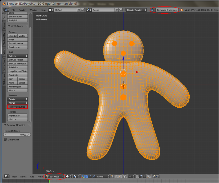
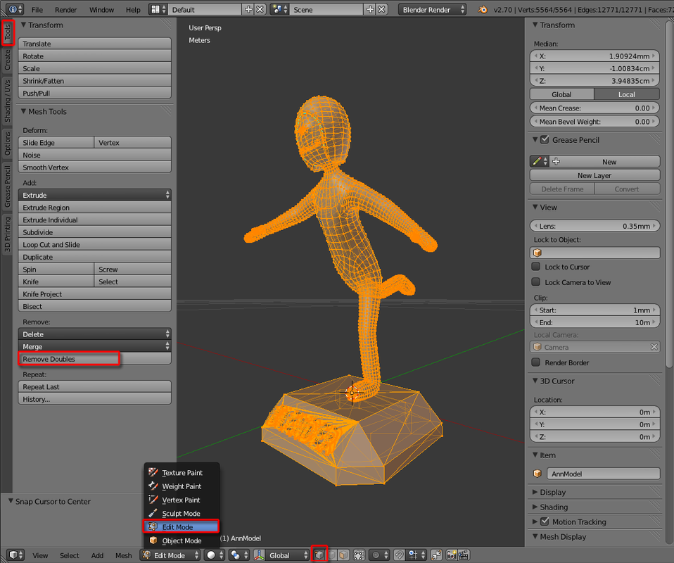
28. Switch to “Edit Mode” and select all Vertices (with “Select Vertex” highlighted, hit A once), then hit 'Remove Doubles' under the “Tools” panel.
28. 切換至編緝模式並選取所有點(按A鍵即可),於 “Tools”分頁下按 'Remove Doubles'
28. 切換至編緝模式並選取所有點(按A鍵即可),於 “Tools”分頁下按 'Remove Doubles'
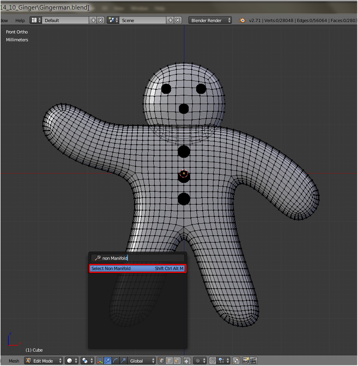
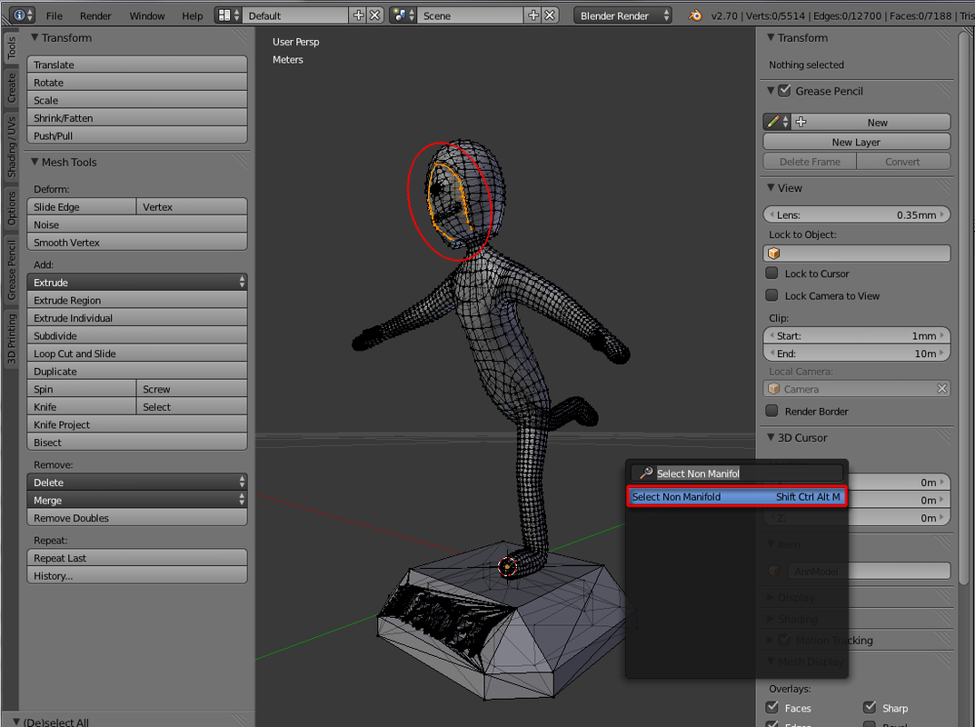
29. Unselect all vertices, hit 'Spacebar' to launch the search box, type in “Select non manifold” and click the displayed “Select Non Manifold” to get all overlapped vertices highlighted. Fix them by deleting all extra vertices, edges and/or faces.
29. 再按A取消全選,按空白鍵,鍵入 “Select non manifold” ,點擊結果,即可選取所有有問題點。刪除這些問題的點/線/面
29. 再按A取消全選,按空白鍵,鍵入 “Select non manifold” ,點擊結果,即可選取所有有問題點。刪除這些問題的點/線/面
30. Before exporting the mesh, goto ‘3D Printing’ tab again and apply “Check All” once more to make sure no ‘Non Manifold Edges” and other major issues (Rotation is in “0” and dimensions fit this workshop limitation).
30. 前往3D printing分頁,點擊 “Check All”確保沒有任何Non Manifold Edges或其他重要問題(旋轉需為0,大小需於限制內)
30. 前往3D printing分頁,點擊 “Check All”確保沒有任何Non Manifold Edges或其他重要問題(旋轉需為0,大小需於限制內)
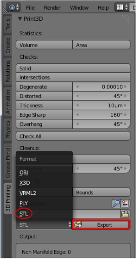
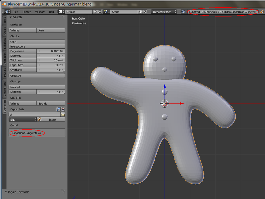
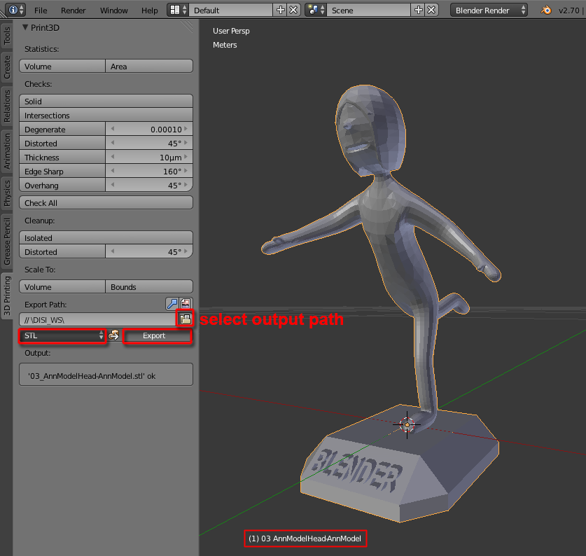
31. Under the "Export Path" inside 3D Printing panel, hit the folder icon and select your output path, then choose “STL” as output type (for this workshop, only .STL be accepted) and finally hit “Export”. You can then try importing your .stl into Blender to preview it (in this workshop, we’d use another program to verify your .stl).
31. 於Export Path一欄下,點擊文件夾圖示選定輸出路徑,選STL為輸出格式(此workshop只用STL格式打印)最後按Export。你可以嘗試導入該STL檔查看檔案效果(我們將使用另一個程式核證你的STL檔)。
31. 於Export Path一欄下,點擊文件夾圖示選定輸出路徑,選STL為輸出格式(此workshop只用STL格式打印)最後按Export。你可以嘗試導入該STL檔查看檔案效果(我們將使用另一個程式核證你的STL檔)。
** Upload your .STL to us BEFORE 9:00am on 15th July, 2014 (late submission would not be printed!)
**請於2014年7月15日早上9:00前上傳你的STL檔(逾期不候)
Attend the last session of this workshop on 19th July, 2014 to check out your .stl model and learn the technologies about 3D printing from our university’s Industrial Center.
請於2014年7月19日出席最後一課以作最後核證你的STL檔,我們將於理工大學工業中心內講解3D打印技術。
請於2014年7月19日出席最後一課以作最後核證你的STL檔,我們將於理工大學工業中心內講解3D打印技術。
