
|
Blender Introduction Workshop -
3D Modelling (26/May/2018) |
|
|
|
Acknowledgements
Special Thanks to Mr. Magnum Chau and everyone who helped and made it happen!

Blender Basics
Pls. refer to "I MAKE 01" workshop to learn Blender's Interface
|
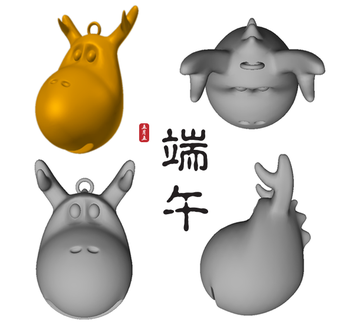
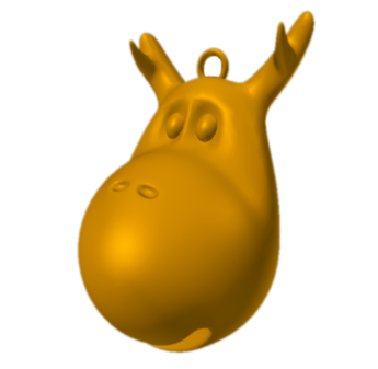
Dragon's Head Keychain
|
|
|
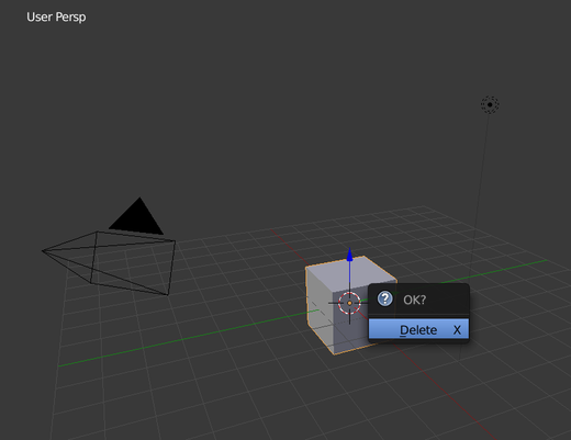
1. Select the default cube and 'Delete' it
|
|
|
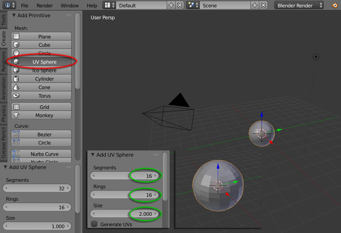
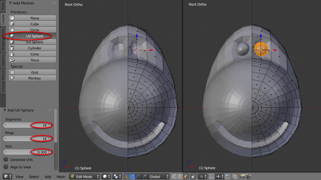
2. Create a 'UV Sphere', then
input variables: Sigments: 16 Rings: 16 Size: 2 |
|
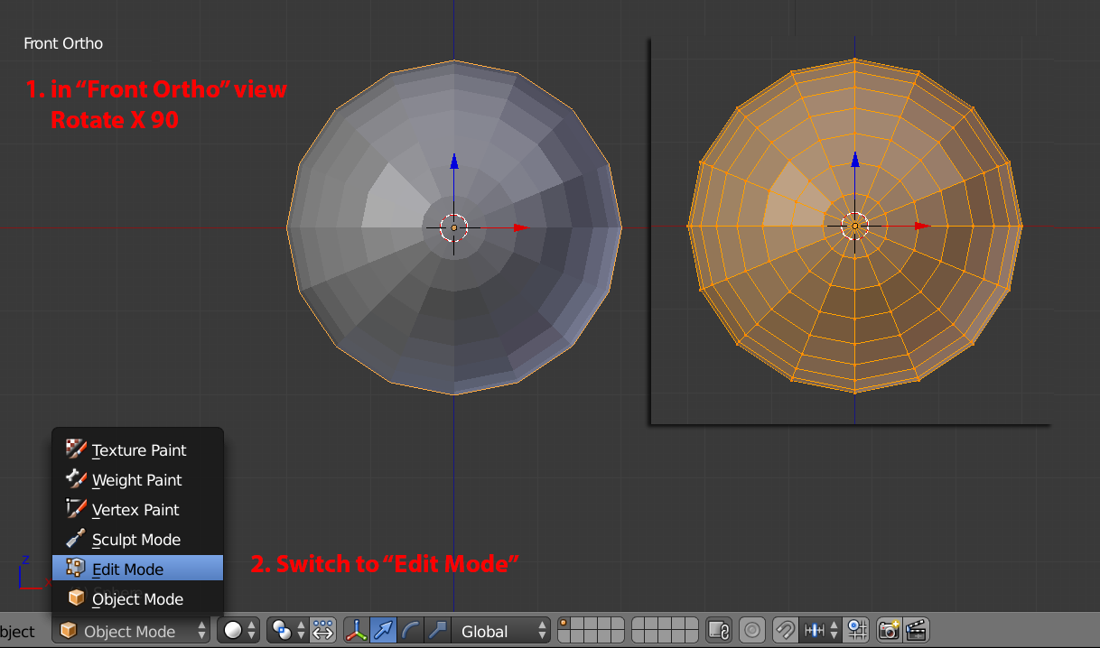
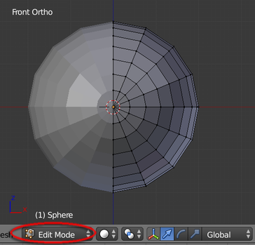
3. In the "Front Ortho" view, hit "R" key, then type "X" and input "90". Yet, switch to "Edit Mode"
|
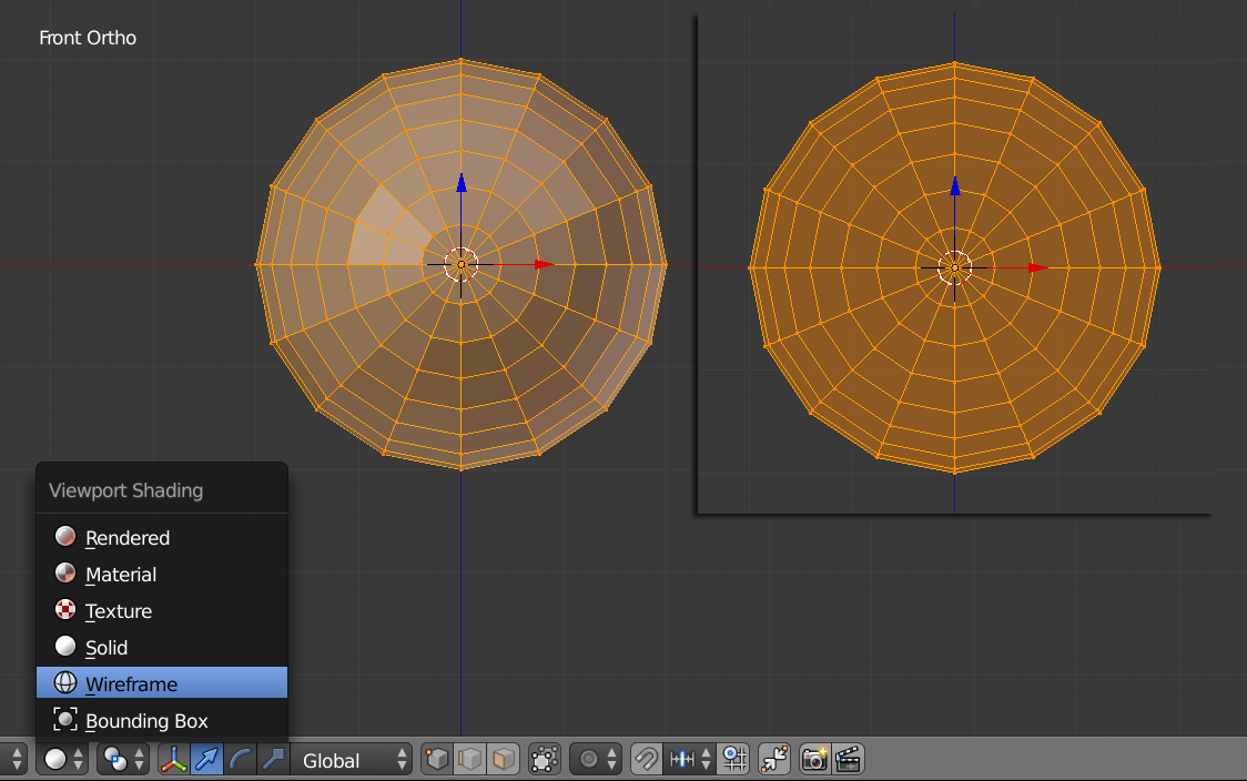
4. In the "Viewport Shading" menu, switch to "Wireframe"
|
|
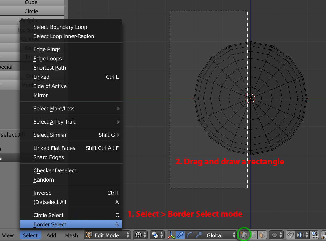
5. In menu Select > Border Select, then Drag mouse to draw a rectangular box to select ONLY the left-hand side vertices
|
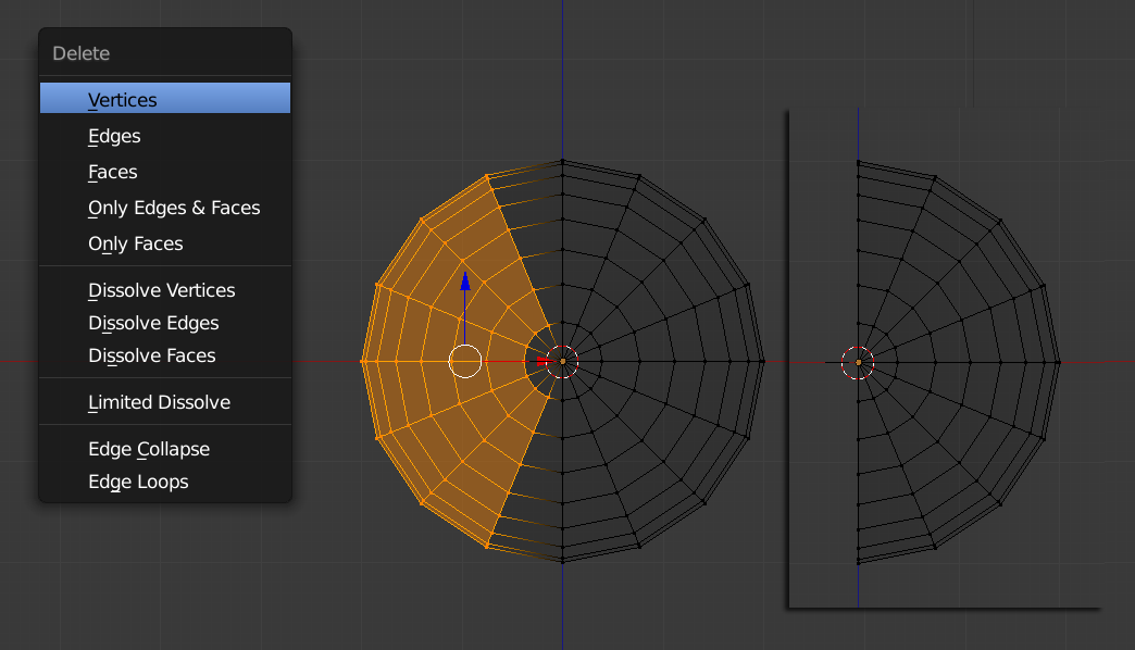
6. Hit "X" key and select "Vertices" to delete the left hemisphere
|
|
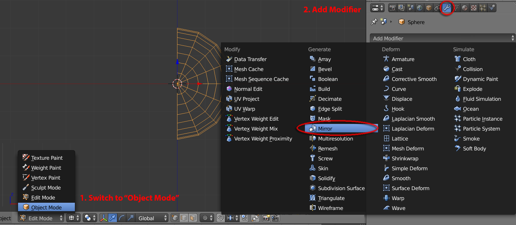
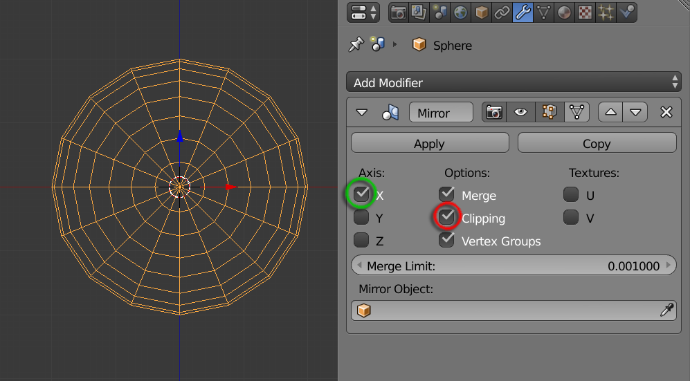
7. Switch to "Object Mode". Add a "Mirror" Modifier. And inside the Property panel, check "Clipping"
|
Make sure it's Axis is "X" and all options are checked
|
|
|
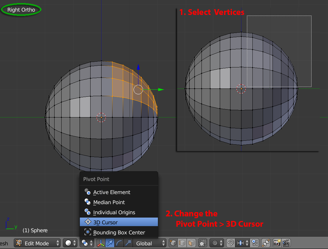
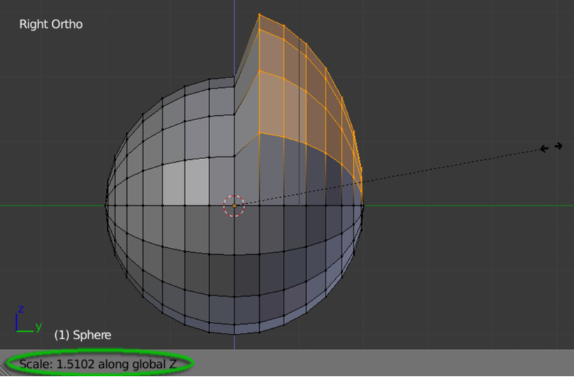
8. Switch to "Edit Mode". Use or Change to "Right Ortho" view, hit "B" key to border select the top-right corner's vertices. Then, change the "Pivot Point" to "3D Cursor"
|
|
9. Hit "S" key following "Z" and drag mouse to scale upto about 1.5
|
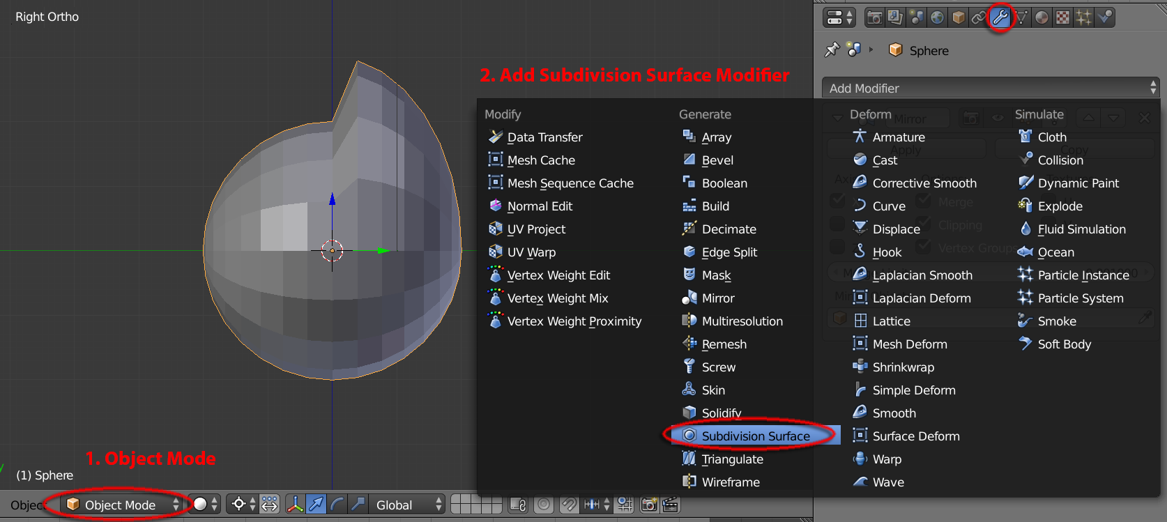
10. Switch to "Object Mode". Add modifier "Subdivision Surface"
|
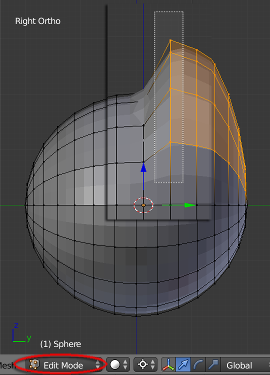
11. Switch to "Edit Mode". Un-Select the first column of scaled upward vertices by firstly hit "B" key, then hold the "Shift" key to drag ONLY the first column
|
|
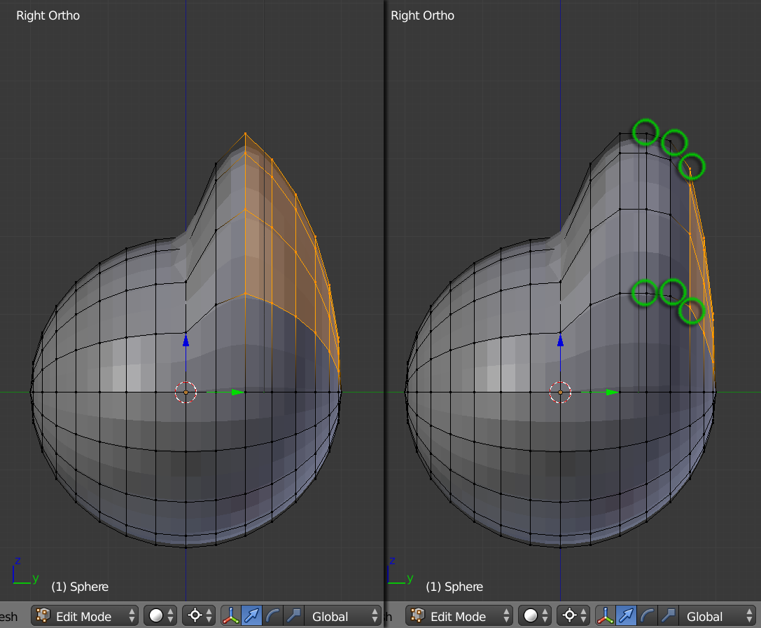
12. Once first column is un-selected, hit "S" key following "Z" key and drag the mouse a little bit to carefully sculpt the form of forehead.
13. Repeat Step 12 for the second column, then third and forth until you are happy with its shape |
|
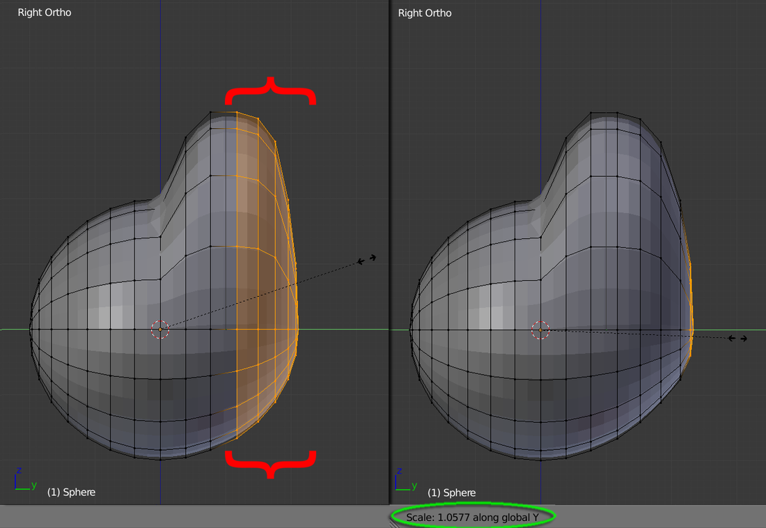
14. Use "A" key to clear all selections. "Border Select" the back of the head's vertices and Scale-Y this time to sculpt a rounded shape head (column by column if you're comfortable doing so)
|
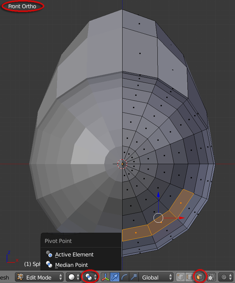
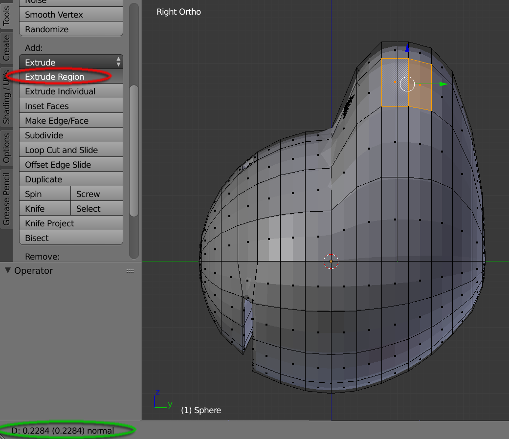
15. Hit key “1” to view the "Front Ortho" view. Change the Pivot Point to “Median Point”. Switch to “Face Selection” mode and select the mouth’s faces. In the “Tools” menu, hit “Extrude Region” to apply a mild extrusion (around Depth: -0.09). Then apply another “Extrude Region” with about Depth: -0.7
|
|
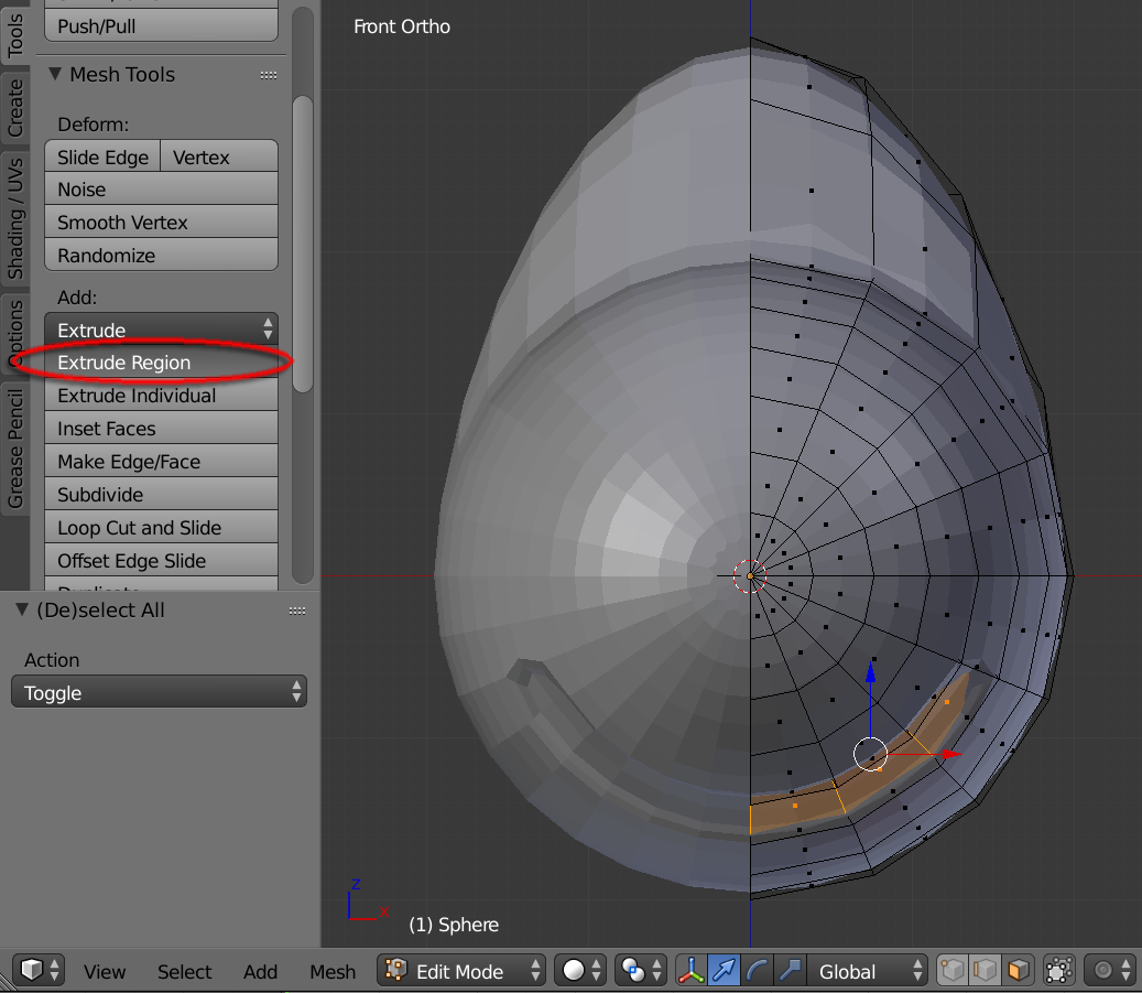
After clicking "Extrude Region", drag the mouse and see Depth is set to around -0.09
|
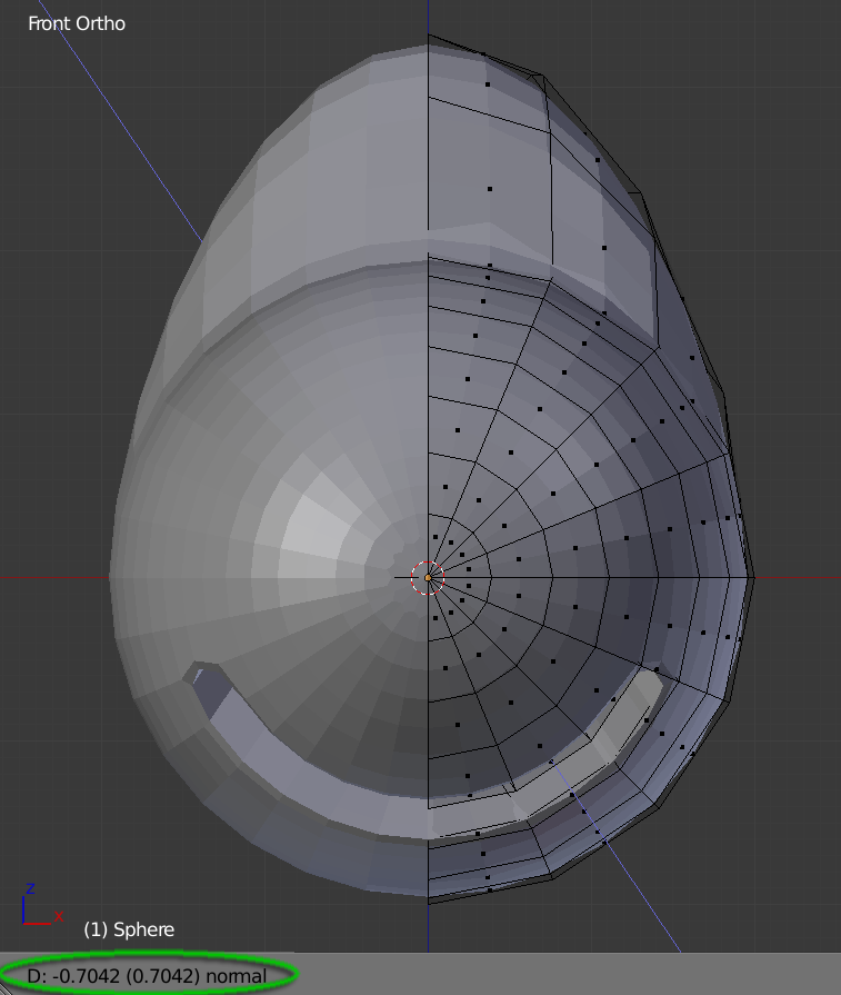
The second Extrude Region should have about -0.7 for Depth value
|
|
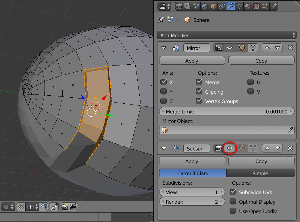
16a. Inside the “Subsurf" Modifier panel, un-check the “eye icon" to deactivate this modifier. Then carefully select all inner mouth faces
|
|
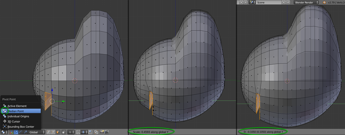
16b. Switch "Pivot Point" to “Median Point” and use “Right Ortho” view. Scale-Y to about 0.45. Then Grab-Y to about -0.1
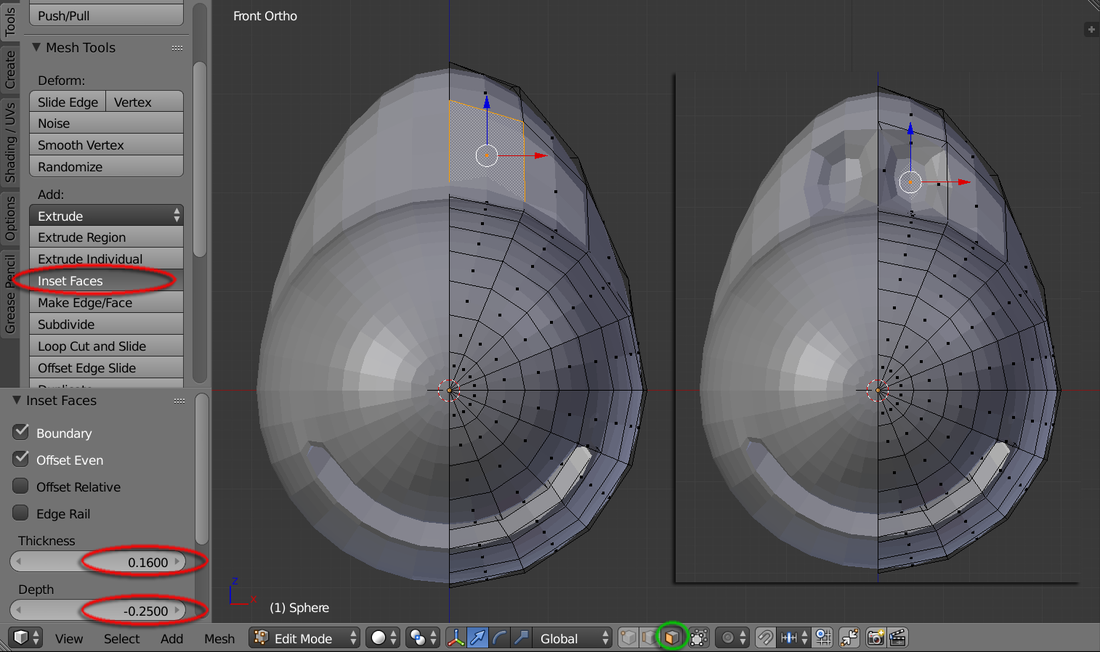
17. Use “Front Ortho” view and "Face Mode". Select the eye socket face. In “Tools” menu, Add: “Inset Faces” and input value “0.16” for Thickness, and "-0.25” for Depth
|
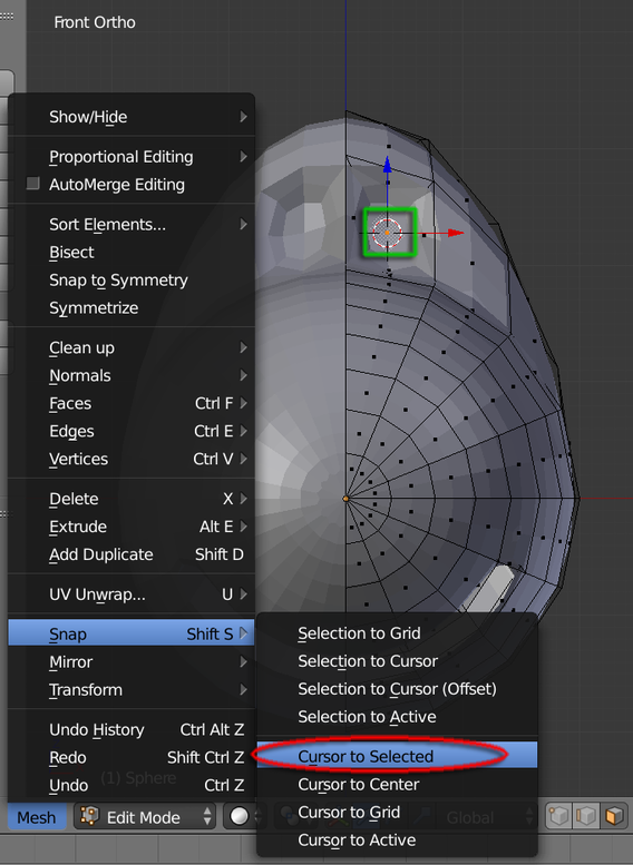
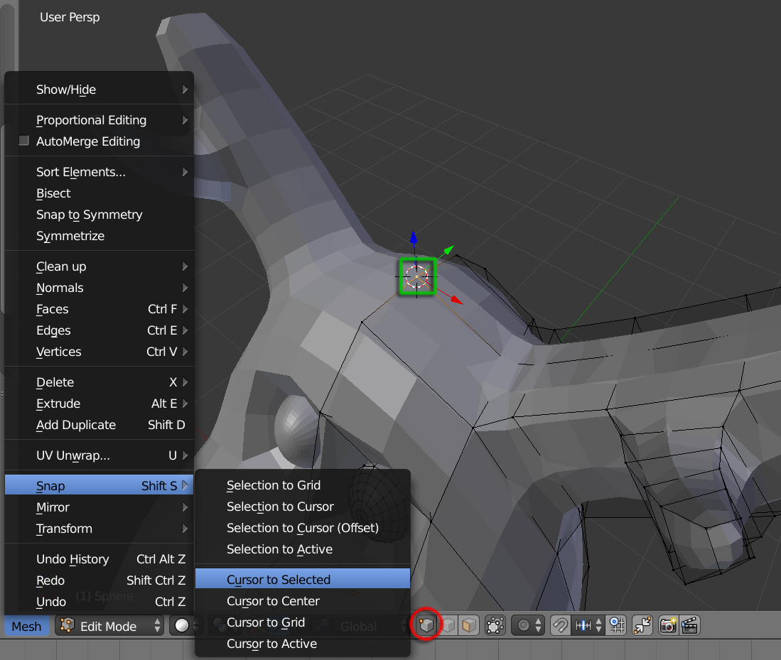
18. Goto Mesh> Snap > Cursor to Selected and you’d see the Cursor now snap to this position
|
|
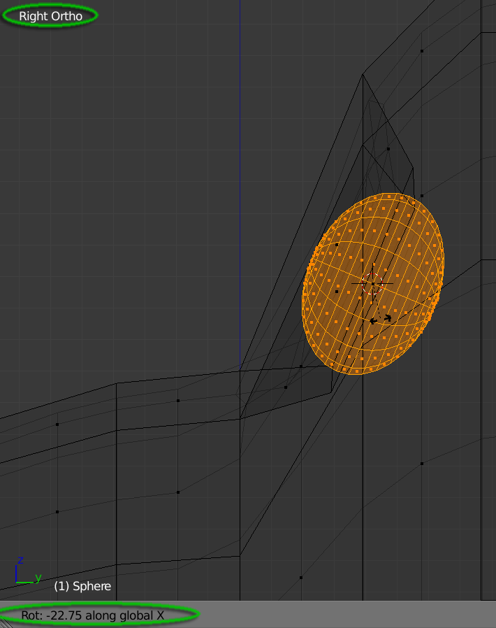
19. Create > UV Sphere and input following variables: Segments and Rings to “16” and Size “0.3”. Rotate-X 90 and then firstly Scale-X “0.8”, then Scale-Y “0.7”. In “Right Ortho” view, Hit “R” key, then drag to about -22.75 and parallel the eye-ball to its socket surface
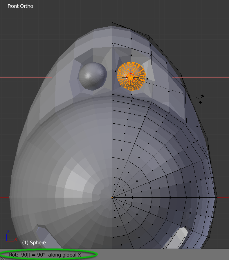
"R-X-90"
|
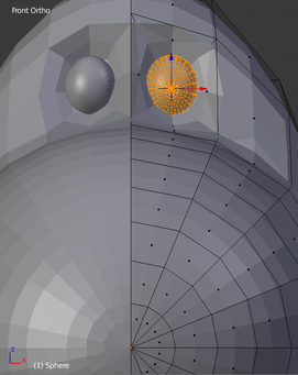
"S-X-0.8", then "S-Y-0.7". Use "3" viewport, "R" and drag to align the eyeball
|
|
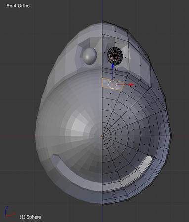
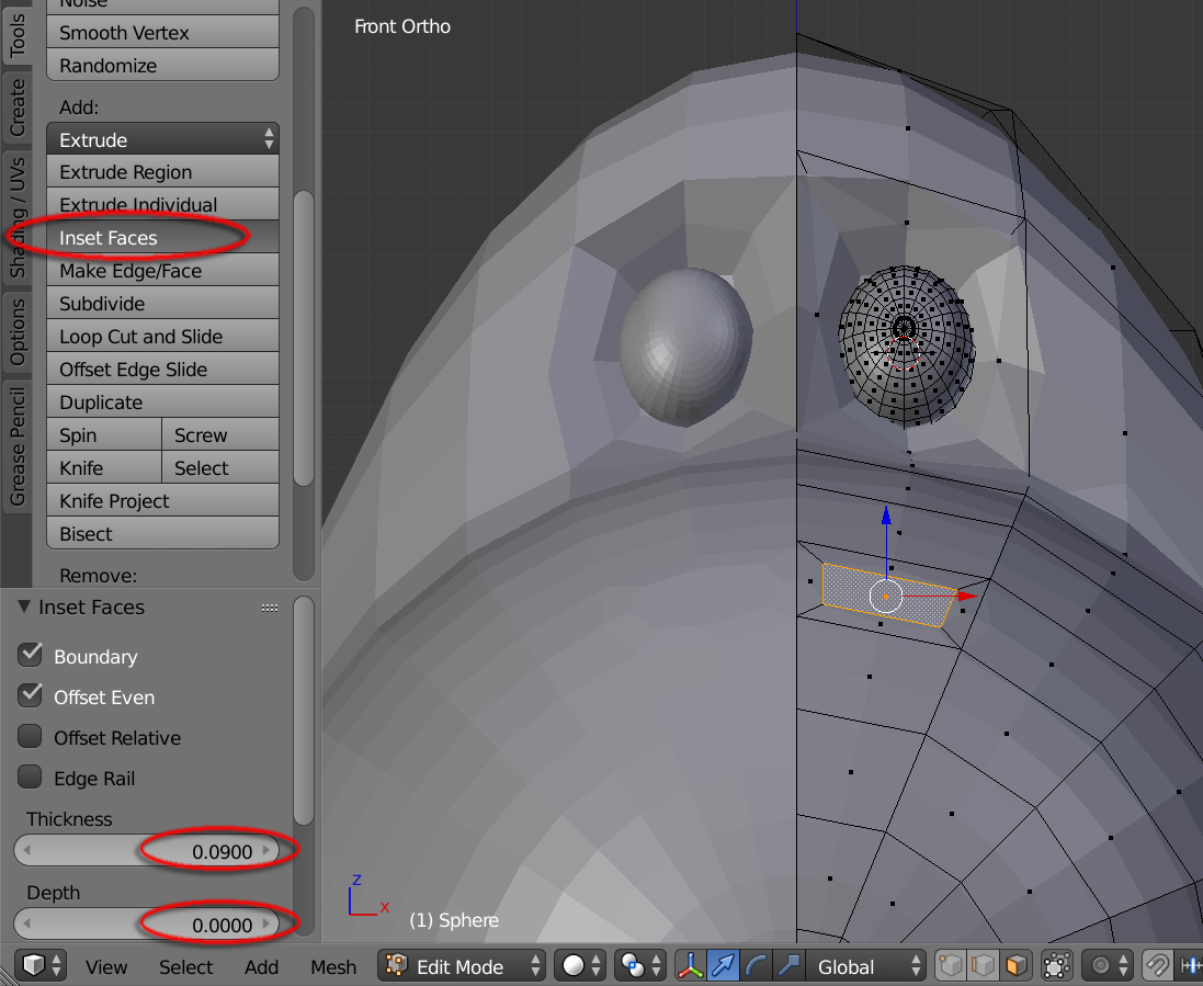
20. Use “Front Ortho” view, Select the nose face. Goto Tools > Inset Faces and input “0.09” for Thickness and “0” for Depth.
|
|
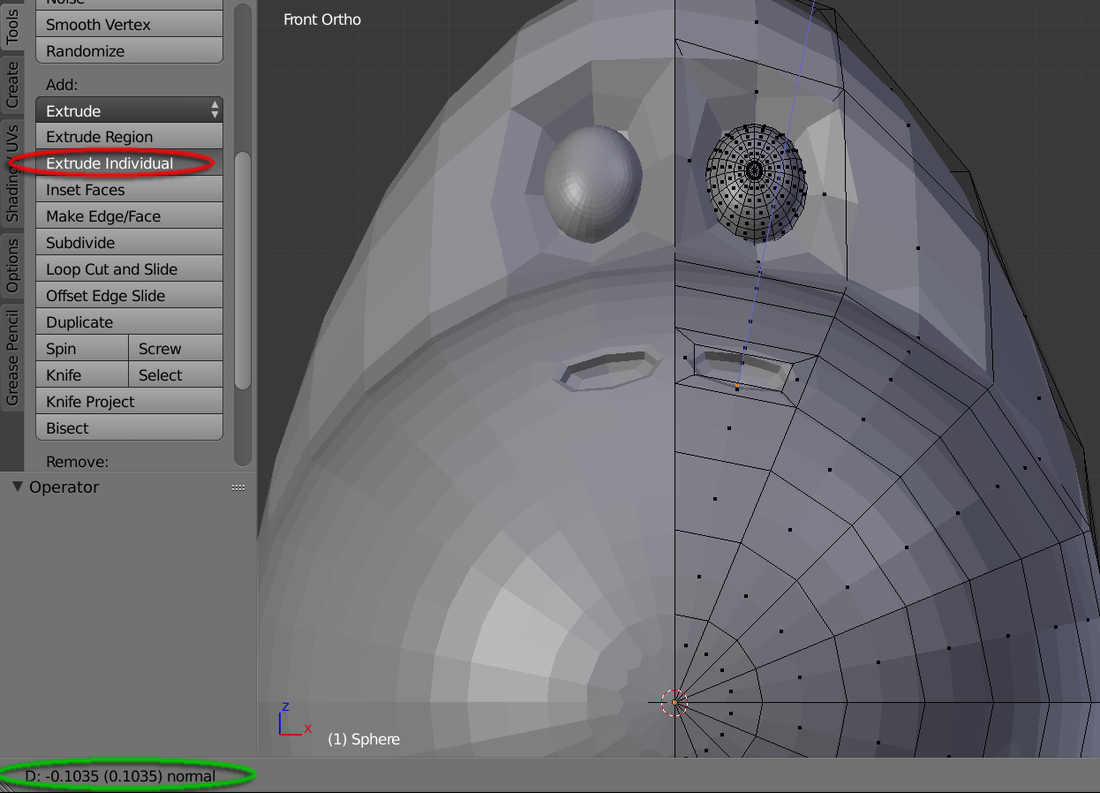
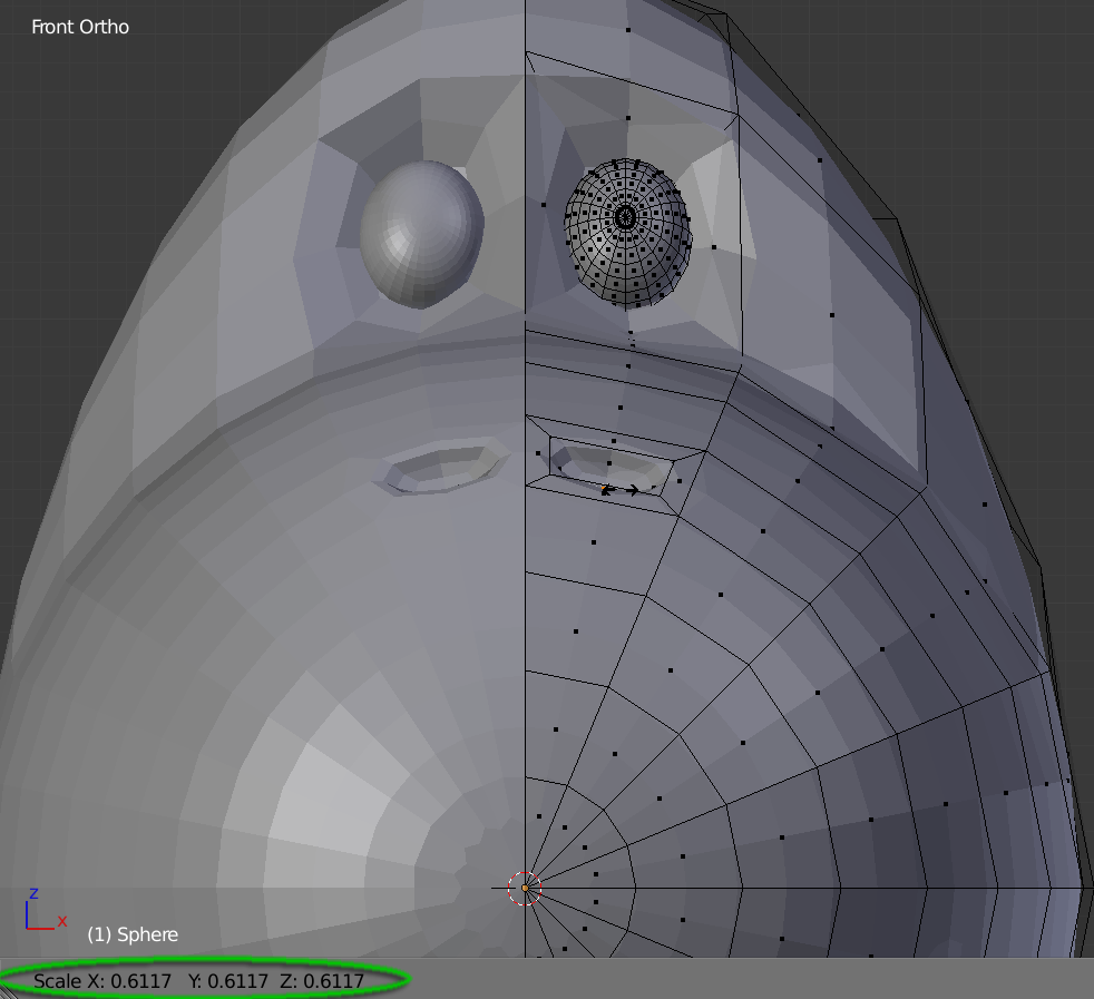
21. Tools > Extrude Individual and drag to about “-0.1” for depth value. Hit “S” key and drag to about 0.6
|
|
|
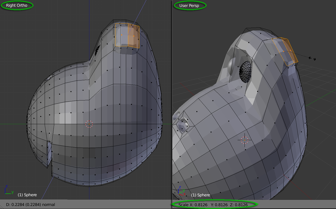
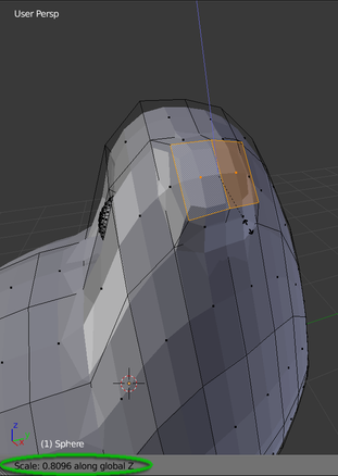
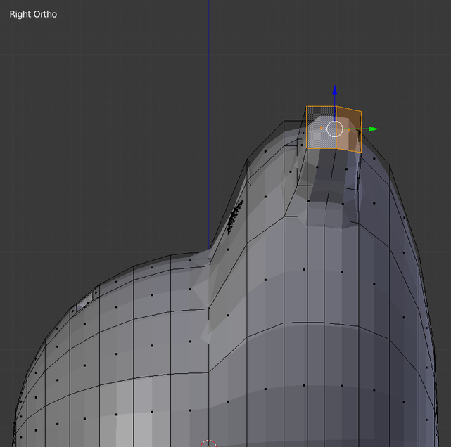
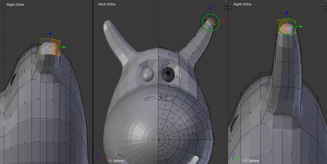
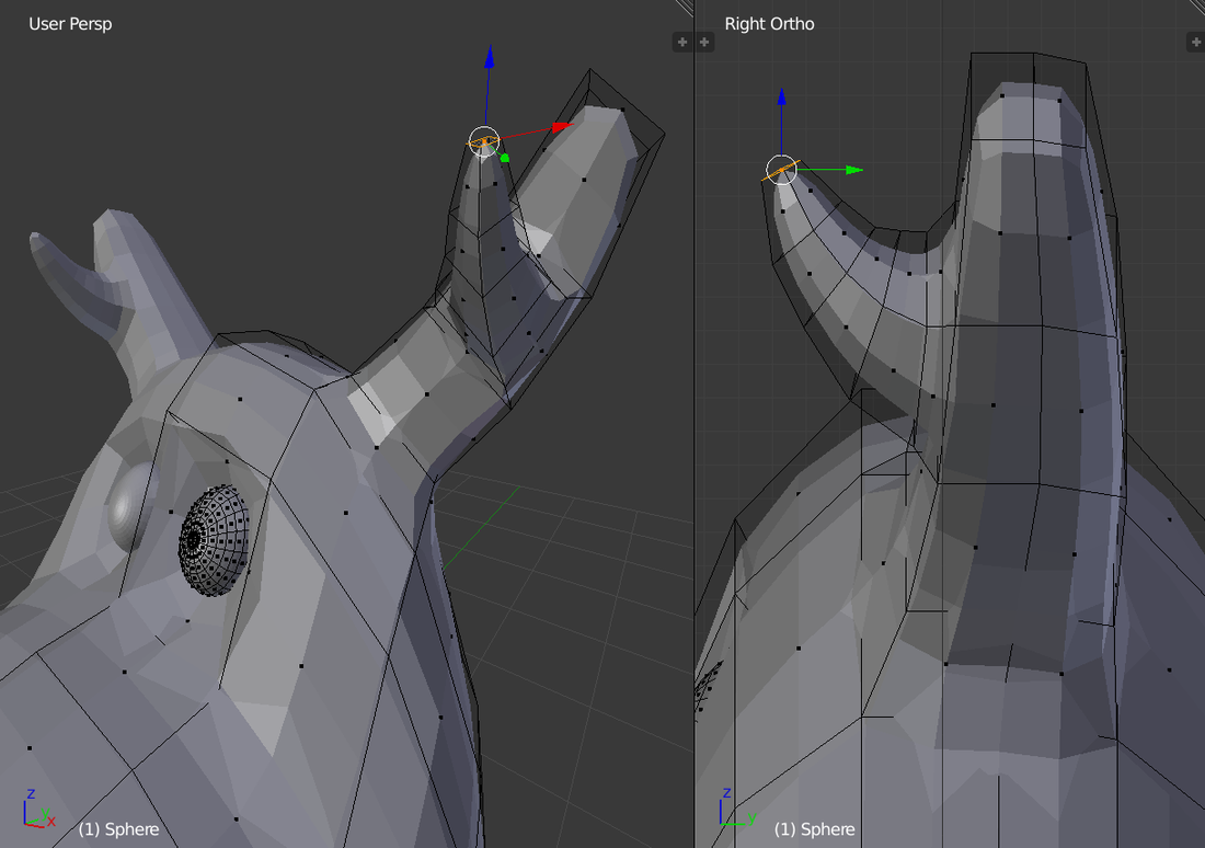
22. In "Right Ortho" view, Select the dragon horn’s faces. Tools > Extrude Region and drag to about 0.2 for depth. Use other view ports to preview result and hit “S” key and drag to about “0.8”.
Then hit “S” then “Z” key and drag to about “0.8” to make it a square-like shape |
|
|
"S-Z-0.8" to form a squared horn shape
|
23. Use other view ports or Orbit to preview result. Repeat the extrude feature hitting “E” key, drag to about 0.5 for depth, and hit “S” key to drag to about 0.9 to scale it down.
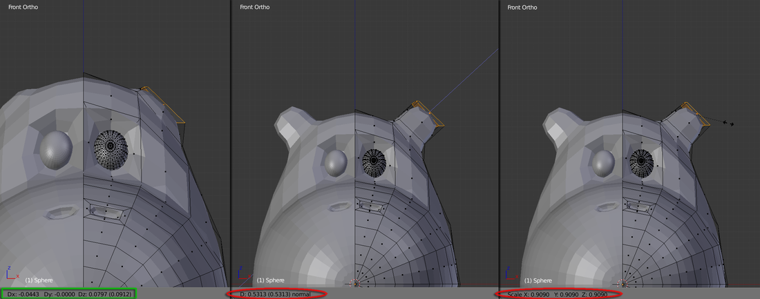
In “Right Ortho” view, Hit “G” then “Y” key to slide it to the right position
24. Repeat Step 22 and 23 two more times and use "E", “G” and “S” keys to sculpt the shape and form the horn (I used about 0.5 for depth and about 0.9 / 0.8 / 0.5 for Scale to sculpt the following shape)
*You can skip this step if you're not very comfortable with "extrude", "rotate" and/or "scale" operations!
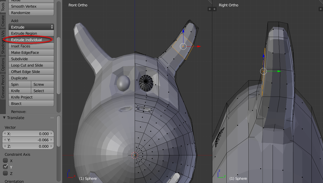
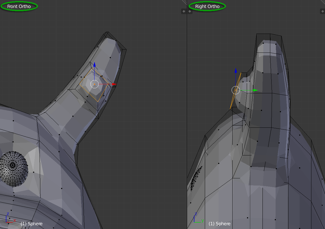
25. Select its Front and Middle face to create a branch. Tools > Extrude Individual and this time rotate a bit more to bend this branch towards the front (I used about “0.16” for depth and about "0.85" for scale)
25. Select its Front and Middle face to create a branch. Tools > Extrude Individual and this time rotate a bit more to bend this branch towards the front (I used about “0.16” for depth and about "0.85" for scale)
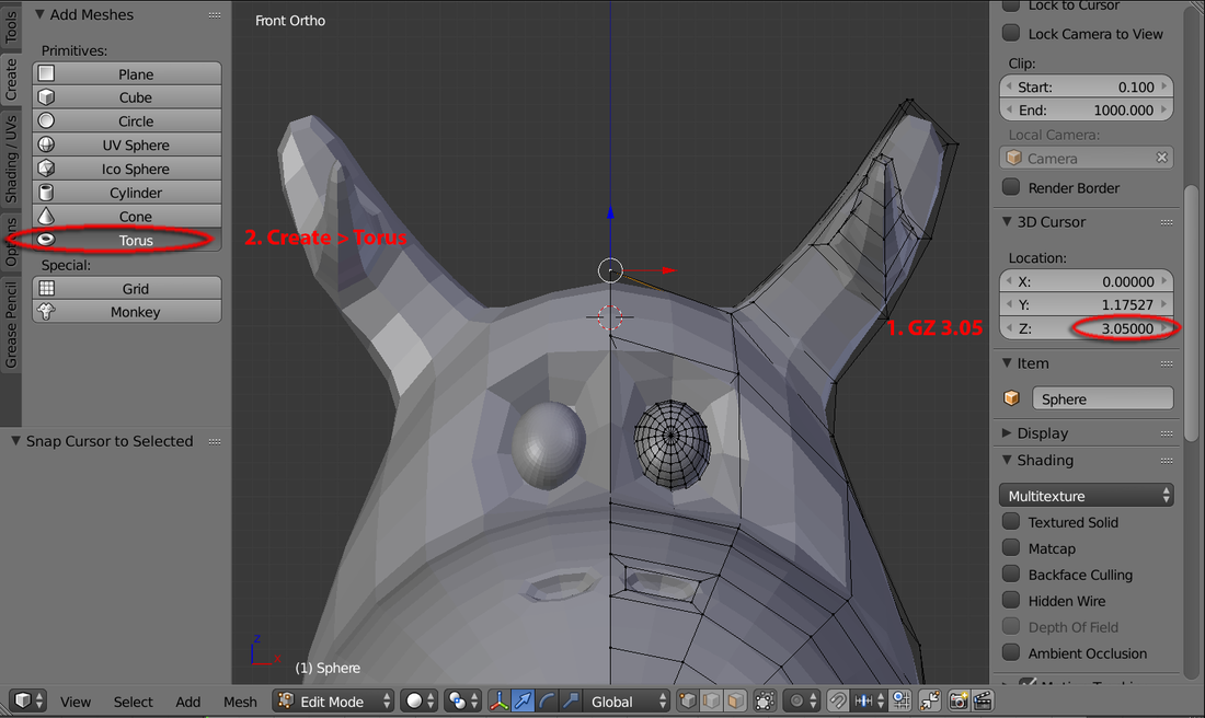
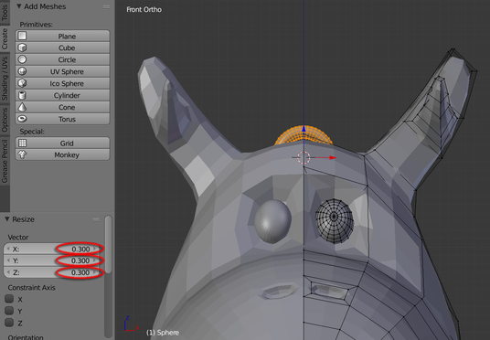
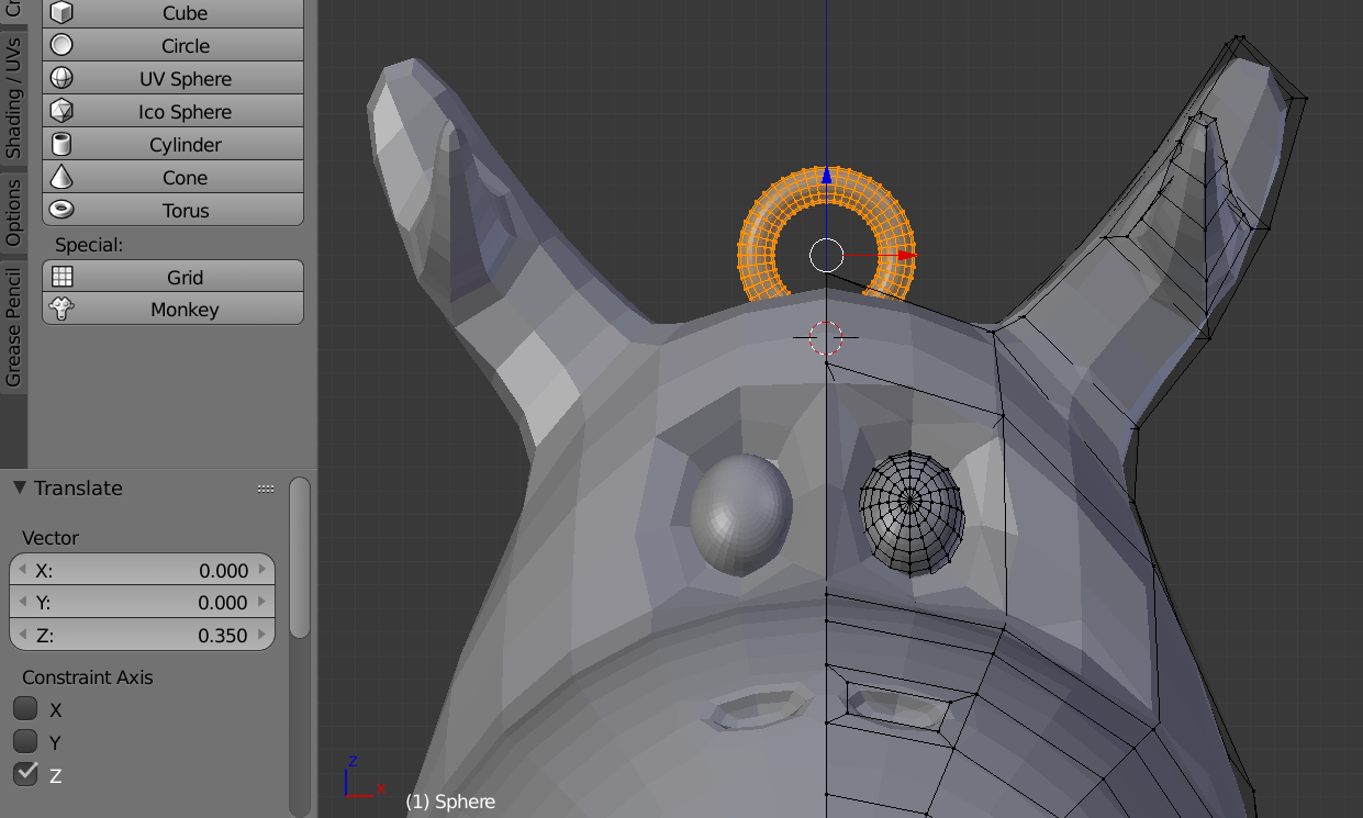
26a. Switch to “Vertex mode". Select the top vertex on top of the head. Mesh > Snap > Cursor to Select and you should see the Cursor will park to it. In “3D View’s Property Panel” (refer to second image underneath), slide the 3D Cursor’s Location Z to about 3.05 (locate it at the front of its forehead). Then Create > Torus.
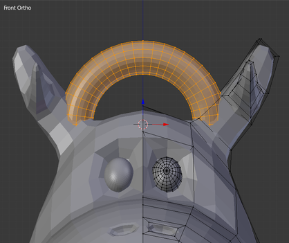
26b. Hit “R” then “X” key and input “90”. Then hit “S” and input 0.3 to shrink its size. Use “G” and “Z” key to slide it to the right position
|
|
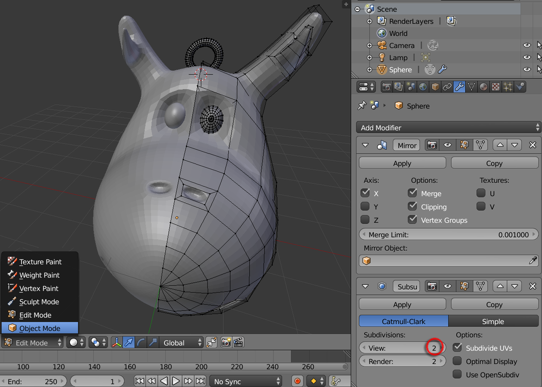
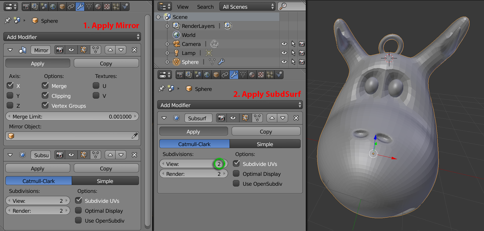
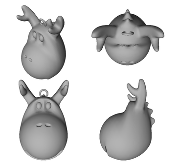
27. Switch to “Object Mode” and inside “Subsurf” modifier panel, increase Subdivisions: View to “2”. Firstly hit “Apply” to the Mirror modifier, then hit “Apply” for the Subsurf modifier to complete the process (Refer to the bottom image underneath)
** You can use the “Mesh: 3D Print Toolbox” Add-ons to check on the geometry and export it in .stl format for 3D printing file. Feel free to D/L the open source “osmmDragon.stl” if wish
|
Download our .stl
|
| ||
